Appendix C
A-64
To use the slide track:
1. Complete steps 1 through 3 in Section 4.2 to determine the transducer spacing.
2. Ensure that the inside face of the left transducer is aligned to the 0 (zero) spacing mark.
If not, loosen the thumb screws and adjust its position accordingly.
3. Loosen the thumb screws on the right transducer.
4. Move the right transducer until the inside face of the transducer lines up with the
spacing measurement provided in Menu 25.
5. Tighten the thumbscrews to lock the transducers in place.
6. Follow steps 4 through 10 in Section 4.2 to complete the installation.
NOTE:
The slide track is mounted to the pipe as a single assembly.
4.3 Aligning the Transducers
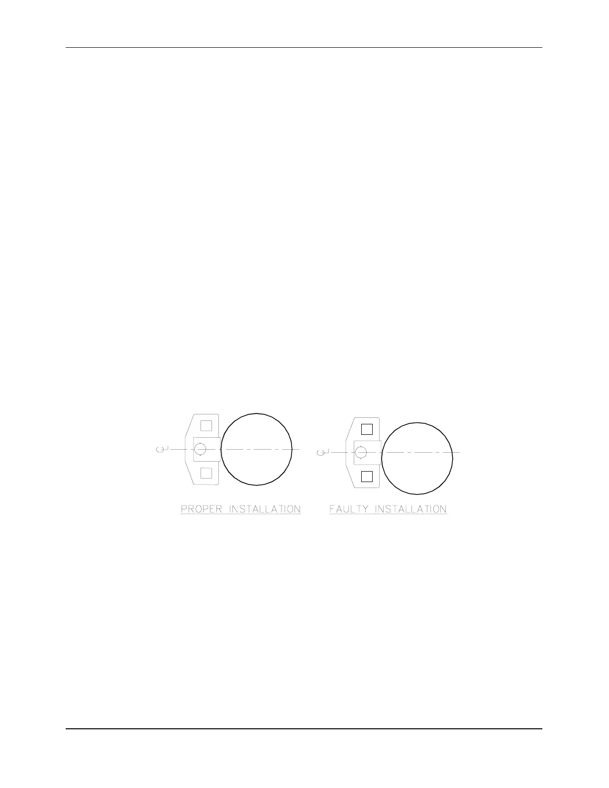
The most critical requirement of transducer alignment is that the transducer face be aligned
normal to the pipe. This is particularly critical on small pipes due to pipe curvature. Figure
4-3 shows a properly installed transducer and a one that has been installed improperly.
Notice that the properly installed transducer contacts the pipe at the pipe’s centerline and
that the gaps on either side of the centerline are equal.
Figure 4-3 Aligning the Transducers
The easiest method of aligning transducers on small pipes is as follows:
1. Secure both transducers to the pipe with the metal bands, tightening the bands until the
transducers are just snug.
2. Adjust the transducers until the gaps on both sides of the transducers are equal.
3. While holding the transducers in place, tighten the bands sufficiently to prevent the
transducers from slipping and to allow proper operation of the flowmeter.