7088-8000
-165
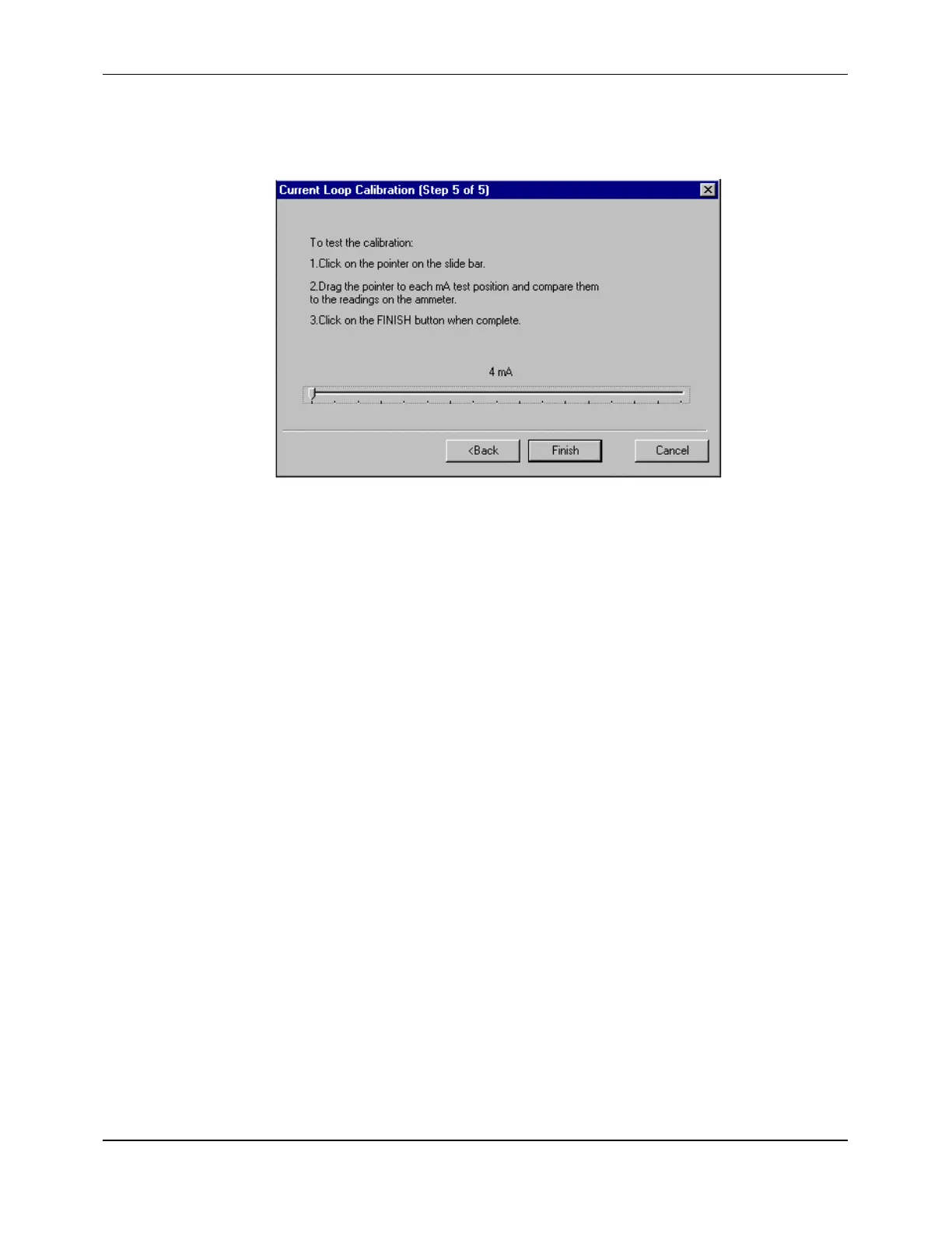
The last Current Loop Calibration screen (Step 5 of 5) is displayed (Figure F-20):
Figure F-20 Current Loop Calibration Screen (Step 5 of 5)
The current loop can be tested by changing the output of the flowmeter and comparing
it to the reading on the ammeter. A slide bar is displayed that represents the 4 to 20 mA
range. The slide bar is scaled in increments of 1 mA, with 4 mA represented on the far
left and 20 mA on the far right. The present output is indicated by a pointer on the bar
with the corresponding numeric value displayed above the bar.
14. To test the accuracy of the current loop, click on the slide bar pointer.
15. Drag the pointer to each test position on the 4 to 20 mA scale and compare them to the
readings on the ammeter.
NOTE:
If testing of the current loop output is all that is required, the test can be
performed on the
4-20 mA
options group screen without entering the
calibration mode. The
4-20 mA
options group screen contains an independent
test slide bar that looks and operates similar to the one displayed in the
calibration mode. To activate the independent test slide bar, ensure that the
TEST/CALIBRATION
check box is checked and follow steps 14 and 15 of this
procedure.
16. If the value displayed above the slide bar and the ammeter do not match, readjust the
calibration and retest it (steps 10 through 15).
NOTE:
To return to the previous screen for repeating steps 10 through 15, click on the
<BACK
command button.
17. Click on the
FINISH>
button when complete.
18. Click on the
SEND
command button to apply the new current loop calibration settings
to the flowmeter.
NOTE:
The current loop output maintains its present value for approximately 30
seconds after exiting the calibration or test function.