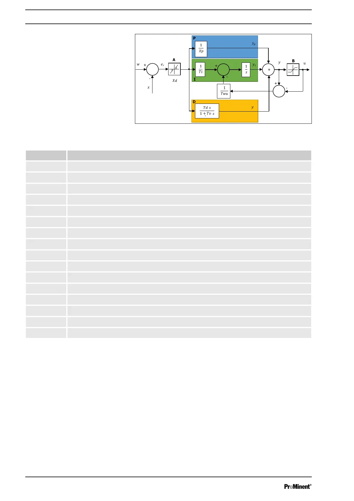
Fig. 102: ‘P.I.D.’ metering mode
Parameter Meaning
A Dead zone
B Output limit
P Calculation of the proportion
IC Calculation of the integral
DC Calculation of the derivative
Xp Reciprocal proportional value
Td Time of the derivative
a Control setpoint
x Measured value
e Control error
y Control requirement
u Metering control
Ti Integral band
Xd Dead band value around the setpoint
Td Filter constant
Twu Anti-saturation
The difference between the setpoint w and the measured value x
corresponds to the control error, which is filtered by a dead zone.
The dead zone A eliminates small control errors. The filtered con‐
trol error is transmitted to the P.I.D. computer, which consists of
three components. Proportional (P), Integral (I) and Derivative (D).
The integral (in green) also has an anti-saturation system to limit
the effect of the integral.
The sum of the three components results in a control requirement
Y, which is limited depending on the actuators B you use (-100
% ... 0 %, or 0 % ... +100 %, or -100 % ... +100 %).
If the integral and the derivative are OFF, the metering mode is
[PROPORTIONAL]
.
If only the derivative is OFF, the metering mode is
[PROPORTIONAL INTEGRAL]
.
When all values are entered, the metering mode is
[PROPORTIONAL INTEGRAL DERIVATIVE]
.
Setting measuring and control parameters
100