4.3.10 Electronic relay outputs (RO1 and RO2)
The electronic relay outputs are primarily intended for the control of
the metering pumps in pulse mode. The electronic relay outputs
can also act as alarm relays, or be controlled in timer mode, as
required.
The electronic relay outputs use electronic components for contact.
The electronic relay outputs are used to drive pumps by their pulse
input or for the control of an external output relay. These relays can
switch a maximum voltage of 48 VAC and maximum current of 50
mA.
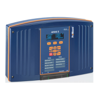
Fig. 23: Electronic relay outputs (RO1 and RO2)
1. Use a 2-lead cable designed appropriately for use for voltage
and power.
2. Remove the protective sleeve of the cable.
3. Strip away 7 mm of the insulation on the leads.
4. Guide the cable through the cable gland.
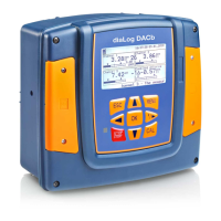
5. Connect the lead to COMMON (25) on the terminal block.
6. Connect the lead to WORK (26) on the terminal block.
7. Tighten the cable gland to make a seal.
1. Use a 2-lead cable designed appropriately for use for voltage
and power.
2. Remove the protective sleeve of the cable.
3. Strip away 7 mm of the insulation on the leads.
4. Guide the cable through the cable gland.
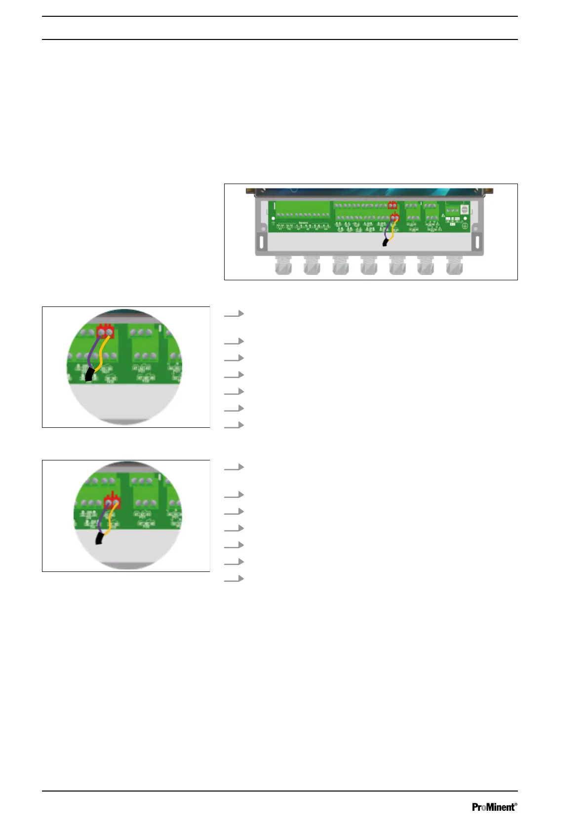
5. Connect the lead to COMMON (39) on the terminal block.
6. Connect the lead to WORK (40) on the terminal block.
7. Tighten the cable gland to make a seal.
4.3.11 4 ... 20 mA output connectors (AO1 ... AO4)
4 ... 20 mA outputs are used to transmit information to a building
management system or control a metering system by a 4 ... 20mA
signal. The analogue outputs are generative and work with an
internal voltage of 12 VDC. The maximum load is 500 Ω. 4 ... 20
mA outputs are fully configurable. They can assign every param‐
eter (measured or calculated) in control or data transmission mode.
Fig. 24: Electronic relay output RO1
Fig. 25: Electronic relay output RO2
Installation and assembly
28