4.3.9 Potential-free relay connections (FO1 and FO2)
The potential-free relay outputs can be controlled as alarm relays,
for control or in timer mode, as required.
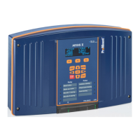
Fig. 20: Potential-free relay connections (FO1 and FO2)
1. Use a 2-lead cable designed appropriately for use for voltage
and power.
2. Remove the protective sleeve of the cable.
3. Strip away 7 mm of the insulation on the leads.
4. Guide the cable through the cable gland.
5. Connect the lead to COMMON (42) on the terminal block.
6. Connect the lead to WORK (41) on the terminal strip or to
REST (43), depending on the function it is to perform.
7. Tighten the cable gland to make a seal.
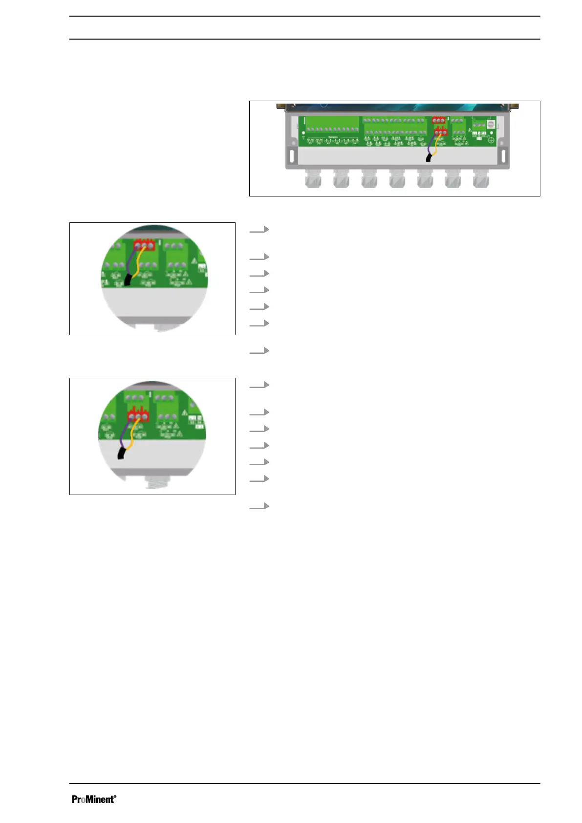
1. Use a 2-lead cable designed appropriately for use for voltage
and power.
2. Remove the protective sleeve of the cable.
3. Strip away 7 mm of the insulation on the leads.
4. Guide the cable through the cable gland.
5. Connect the lead to COMMON (48) on the terminal block.
6. Connect the lead to WORK (47) on the terminal strip or to
REST (49), depending on the function it is to perform.
7. Tighten the cable gland to make a seal.
Fig. 21: Potential-free relay connec‐
tions FO1
Fig. 22: Potential-free relay connec‐
tions FO2
Installation and assembly
27