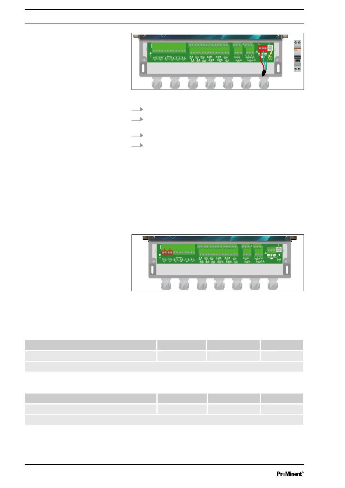
Fig. 8: Primary power supply
3. Guide the cable through a suitable cable gland.
4. Connect the phase to L1 and the neutral conductor to the N
of the main terminal X1.
5. Use an M4 eyelet clamp to connect the earth to the PL1 bolt.
6. Tighten the cable gland to make a seal.
4.3.7 Measuring input connections
The device has 10 inputs:
n 2 potentiometric inputs PI1 & PI2 for pH and ORP sensors,
n 2 inputs AI1 & AI2, 4 ... 20 mA, insulated for temperature,
chlorine or bromine measurement,
n 2 inputs AI3 & AI4, 4 ... 20 mA, uninsulated for temperature,
chlorine or bromine measurement,
n 4 digital inputs DI1 ... DI4 for sensors.
Fig. 9: a) Potentiometric inputs PI1 & PI2
The controller has two potentiometric inputs to which a pH or ORP
sensor can be connected.
Tab. 2: The supported sensors are defined as follows (pH):
pH value 1...12 pH value 0...14 Customer*
pH value (input PI1 or PI2) -• -• -•
(*): The customer’s scale can be defined between -1 ... 15 pH.
Tab. 3: The supported sensors are defined as follows (ORP):
0...1000 mV +/- 1000 mV Customer*
ORP value (input PI1 or PI2) -• -• -•
(*): The customer’s scale can be defined between -1000 ... 1000 mV.
Installation and assembly
20