Note the cabling of the bus system.
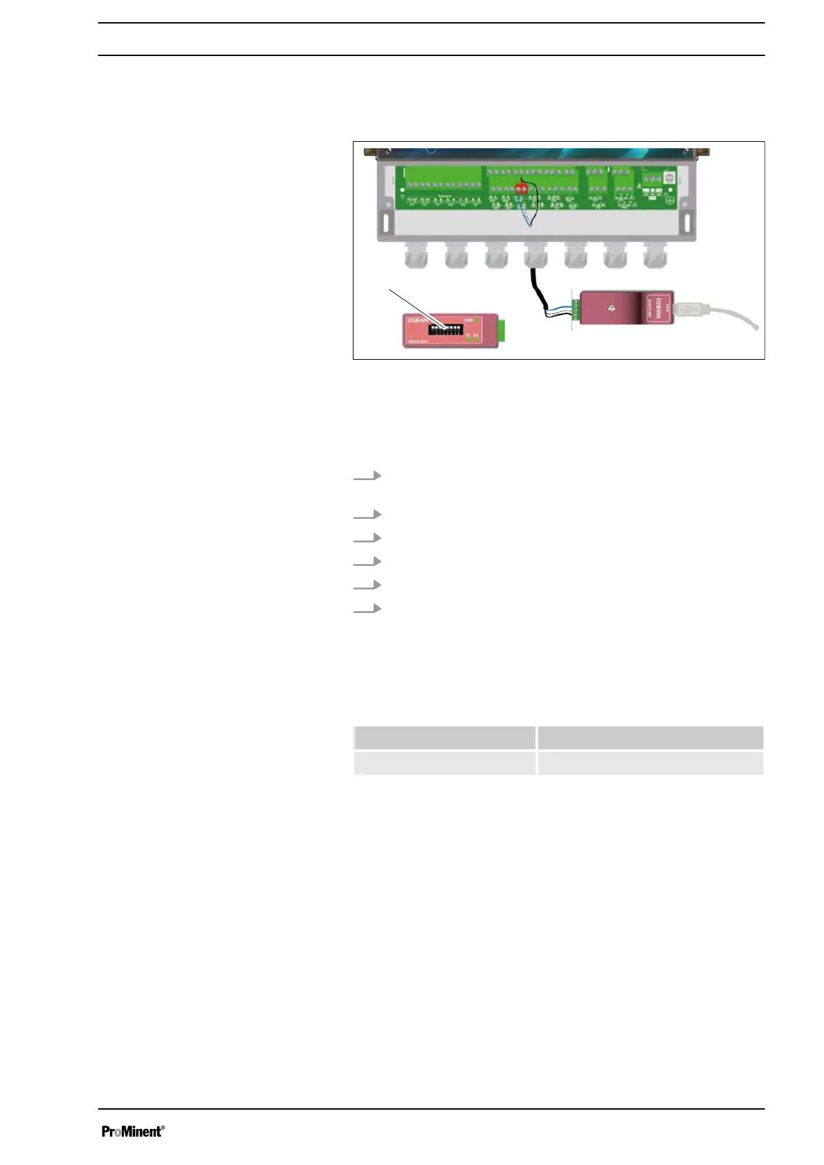
Fig. 55: Connection to the USB port of a computer
Blue (terminal no. 3):
White (terminal no. 4):
Black (terminal no. 5):
Configuration: All switches (1) to "ON".
1. Use a 3-lead cable designed appropriately for use for voltage
and power.
2. Guide the cable through the cable gland.
3. Lead AA (no. 3) of the USB/485 converter to RS485 (A) (31).
4. Lead BB (no. 4) of the USB/485 converter to RS485 (B) (32).
5. Lead C (no. 5) of the USB/485 converter to DWR (C) (18)
6. Tighten the cable gland to make a seal.
A USB/RS485 converter is recommended for connecting the
device to a computer. Please read the documentation on the con‐
verter to connect it up.
Reference Name
INF1021 USB ➨ 485 converter
The devices can be networked noting the order of the cables (par‐
allel wiring).
For safety reasons, it is essential that the device is de-energised
before opening the housing to switch the microswitches.
Connection to the USB port of a com‐
puter
Polarisation and termination of the
RS485 bus
Communication programming instructions
59