PLX51-PBM Operation
PROFIBUS DPV0/DPV1 Master or Slave to EtherNet/IP™ or Modbus® Gateway User Manual
ProSoft Technology, Inc. Page 118 of 196
Extraction
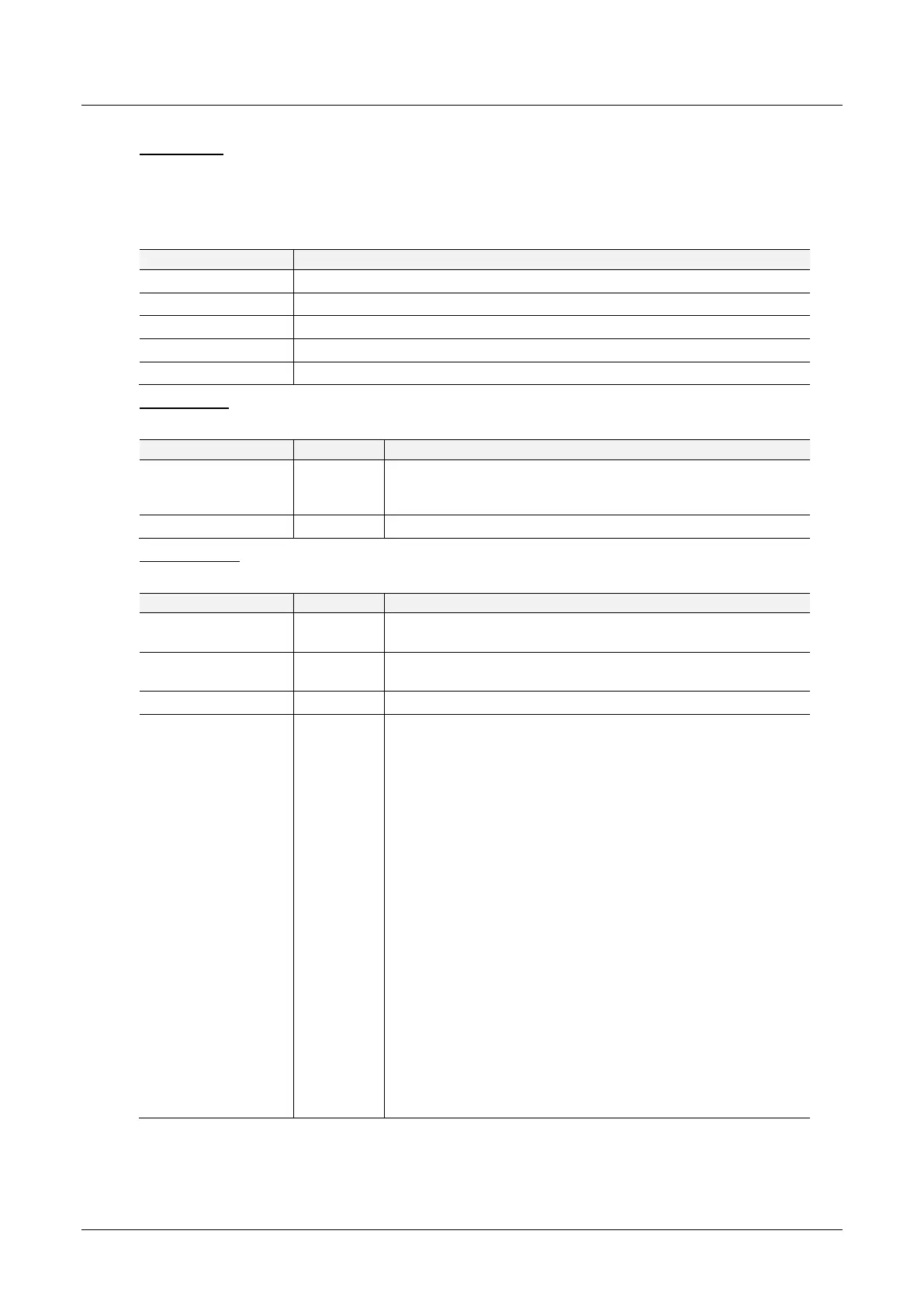
CIP Message
The user can extract an alarm by using the slave device node address. Below are the
EtherNet/IP CIP message parameters as well as the request and response data
structures.
Table 5.34 – Alarm Extract Message
Request Data:
Table 5.35 – Alarm Extract Request
The amount of time (in milliseconds) the PLX51-PBM waits for a
DPV1 response before timing out and responding to the
EtherNet/IP request with a Timeout Status.
The station number of the PROFIBUS device.
Response Data:
Table 5.36 – Alarm Extract Response
This is the status of the DPV1 data exchange. See appendix for
the definitions of the returned status.
This is the extended status of the DPV1 data exchange. See
appendix for the definitions of the returned extended status.
The amount of alarm bytes that have been returned.
Refer to the PROFIBUS Specification EN 50170 for information
regarding the diagnostics.
Below is the basic structure of the alarm data:
Byte 0 – Alarm Type
1 – Diagnosis Alarm
2 – Process Alarm
3 – Pull Alarm
4 – Plug Alarm
5 – Status Alarm
6 – Update Alarm
Byte 1 – Slot Number
Range 0 - 254
Byte 2 - Bit 0 to 1 – Alarm Specifier
0 – No further differentiation
1 – Fault occurred and slot it not ok
2 – Fault disappeared, and slot is ok
3 – One fault disappeared, and slot is not ok
Byte 2 - Bit 3 to 7 – Sequence Number
Range 1 - 32
Byte 3 to 59 – Alarm Data Description
 Loading...

