PLX51-PBM Setup
PROFIBUS DPV0/DPV1 Master or Slave to EtherNet/IP™ or Modbus® Gateway User Manual
ProSoft Technology, Inc. Page 75 of 196
3.9.7 DPV1 Alarms
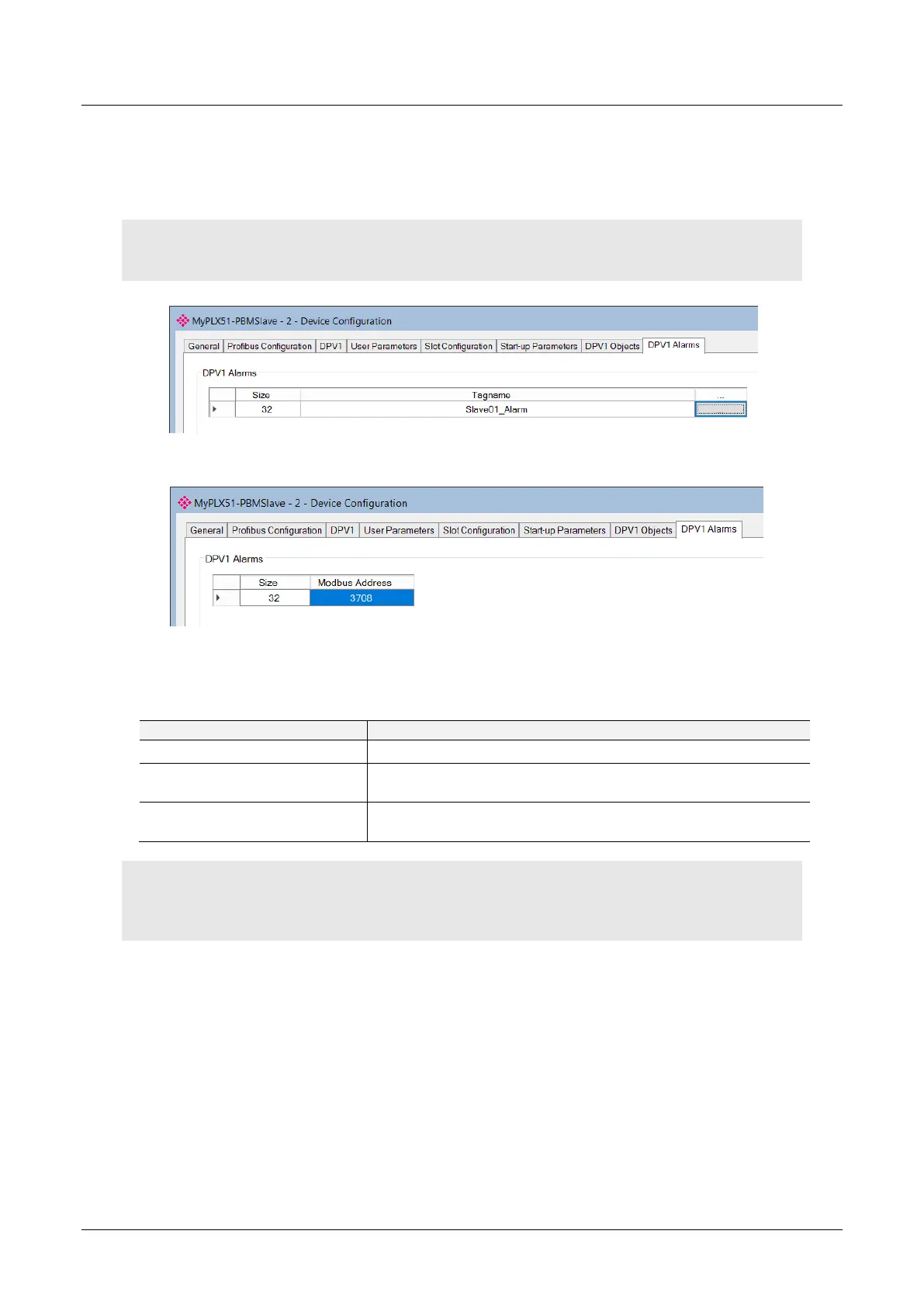
The DPV1 Alarms configuration is shown in the figure below. The slave device DPV1
Alarms configuration window is opened by either double clicking on the slave device
in the tree or right-clicking the slave device and selecting Configuration.
IMPORTANT: The Size of the DPV1 Alarm must be greater than 4 or the alarm triggering will not
execute.
Figure 3.95 – Device DPV1 Alarms configuration parameters (Logix)
Figure 3.96 – Device DPV1 Alarms configuration parameters (Modbus)
The DPV1 configuration consists of the following parameters:
Table 3.21 – Device DPV1 Alarms configuration parameters
The size (bytes) of the Alarm object.
The Logix Tagname from where the alarm data will be read. (Logix
Only)
The Modbus Holding Register Address from where the alarm data
will be read. (Modbus Only)
Note: The DP Master connected to the PLX51-PBM (in slave mode) will be able to configure either of
the following alarms: Diagnostic Alarm, Process Alarm, Pull Plug Alarm, Status Alarm, Update Alarm,
Manufacturer Specific Alarm.