PLX51-PBM Setup
PROFIBUS DPV0/DPV1 Master or Slave to EtherNet/IP™ or Modbus® Gateway User Manual
ProSoft Technology, Inc. Page 73 of 196
3.9.6 DPV1 Objects
The DPV1 Objects configuration is shown in the figure below. The slave device
DPV1 Objects configuration window is opened by either double clicking on the slave
device in the tree or right-clicking the slave device and selecting Configuration.
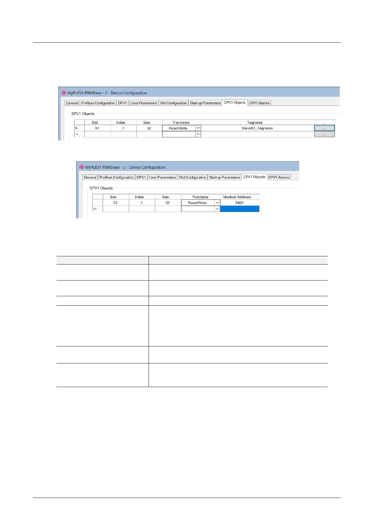
Figure 3.92 – Device DPV1 Objects configuration parameters – Logix
Figure 3.93 – Device DPV1 Objects configuration parameters – Modbus
The DPV1 configuration consists of the following parameters:
Table 3.20 – Device DPV1 Objects configuration parameters
The Slot number to which the PROFIBUS DP transaction will be
directed.
The Index number to which the PROFIBUS DP transaction will be
directed.
The size (bytes) of the transaction.
The Functions supported by the Slave device for this object:
Read
Write
Read/Write
The Logix Tagname where the data will be read / written.
(Logix Only)
The Modbus Holding Register Address where the data will be read /
written.
(Modbus Only)