PLX51-PBM Installation
PROFIBUS DPV0/DPV1 Master or Slave to EtherNet/IP™ or Modbus® Gateway User Manual
ProSoft Technology, Inc. Page 12 of 196
2 Installation
2.1 Module Layout
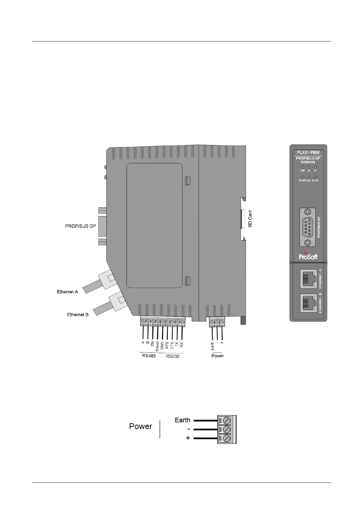
The PLX51-PBM has one RS485 PROFIBUS DP port as well as two Ethernet ports
at the front of the module. The Ethernet cable must be wired according to industry
standards which can be found in the additional information section of this document.
The module provides six diagnostic LEDs as shown in the front view figure below.
These LEDs are used to provide information regarding the module system operation,
the Ethernet interface, the auxiliary communication interface (RS232/RS485), and
the PROFIBUS network status.
Figure 2.1 – PLX51-PBM Front and Side view
At the bottom of the PLX51-PBM module, there is one 3-way power connector and
one 9-way communications connector (the communications connector will be used
for RS232 and RS485 when communicating to Modbus RTU devices).
Figure 2.2 – PLX51-PBM Power connector