PLX51-PBM Setup
PROFIBUS DPV0/DPV1 Master or Slave to EtherNet/IP™ or Modbus® Gateway User Manual
ProSoft Technology, Inc. Page 50 of 196
3.8.3 DPV1
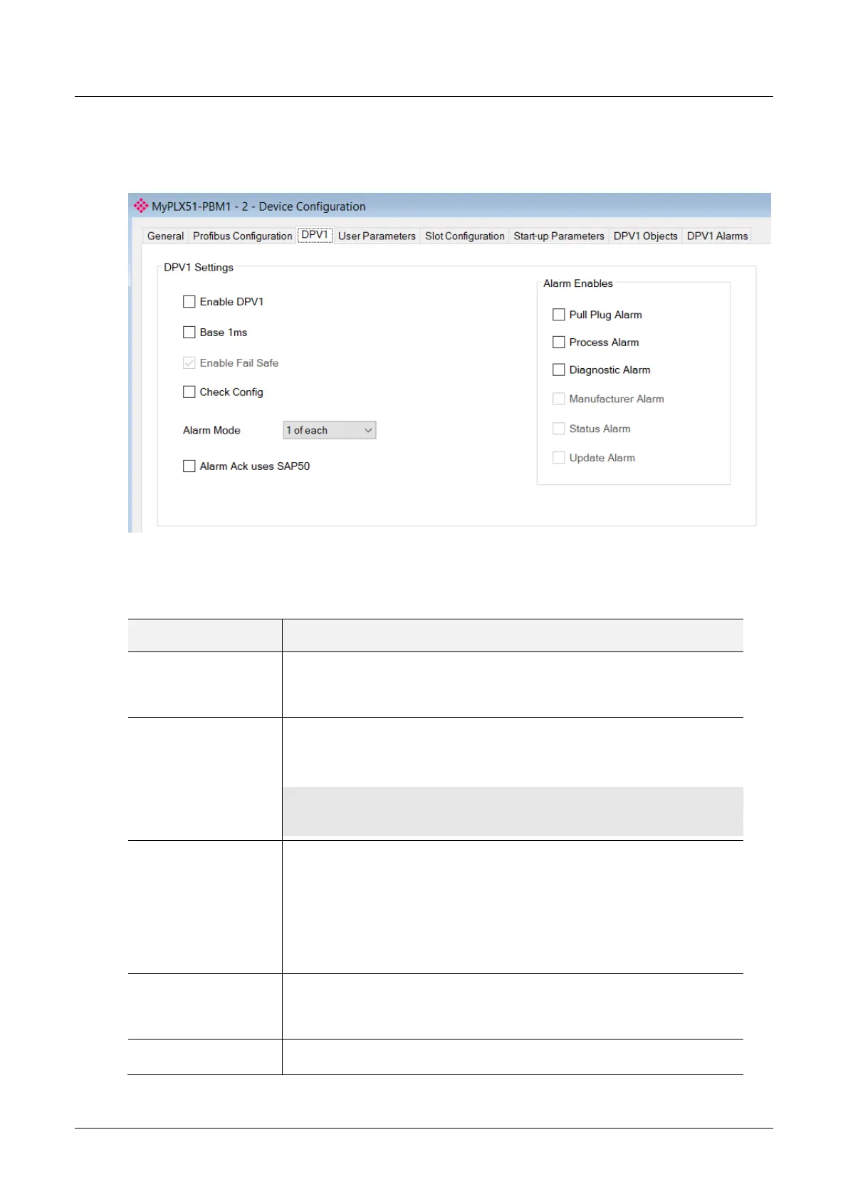
The DPV1 configuration is shown in the figure below. The slave device DPV1
configuration window is opened by either double clicking on the slave device in the
tree or right-clicking the slave device and selecting Configuration.
Figure 3.50 – Device DPV1 configuration parameters
The DPV1 configuration consists of the following parameters:
Table 3.13 – Device DPV1 configuration parameters
Indicates if the slave supports DPV1 Class 1 access (read and write) or
alarms. If the device does not support these DPV1 services, this
parameter must be unchecked. The default value is based on the
information provided by the GSD File.
Indicates if the device should use the 1ms base time for watchdog time
calculation. See the chapter “PROFIBUS Settings” below for watchdog time
calculation.
By default, the field will be unchecked which sets the watchdog base to 10 ms.
NOTE: the watchdog value is always shown in the configuration panel in ms regardless of this
time base setting.
The failsafe mode determines the behavior of the DP Slave outputs when the
PROFIBUS Master is in CLEAR state:
If the slave is configured to be failsafe and supports this feature, then it will
apply its own fallback value (the Master sends outputs with 0 length data)
If not, the Master sends output data at 0
If this feature is supported by the device, the check box must be checked. If
the device does not support it, this parameter must be unchecked. The default
value is based on the information provided by the GSD File.
This checkbox is used to define the reaction to the reception of configuration
data. If the check box is not set, the check is as described in EN 50170. If the
check box is set, the check is made according to a specific user definition. By
default, the field will be unchecked.
This parameter specifies the maximum number of possible active alarms for
the device.