PLX51-PBM Operation
PROFIBUS DPV0/DPV1 Master or Slave to EtherNet/IP™ or Modbus® Gateway User Manual
ProSoft Technology, Inc. Page 128 of 196
5.2 Modbus Operation
When the PLX51-PBM has been setup for Modbus communication it will exchange
data with a remote Modbus device. Depending on the Primary Interface selection, the
PLX51-PBM will either function as a Modbus Master or Modbus Slave.
NOTE: When configured as a Modbus Slave the Modbus Master device will need to read and write all
required data from the configured Modbus address ranges. When configured as a Modbus Master the
PLX51-PBM will automatically update the required Modbus registers in the configured remote target.
5.2.1 PROFIBUS DP - Master
Once the PLX51-PBM and Modbus device have been correctly configured, the
PLX51-PBM will start exchanging data with PROFIBUS slave devices. The user will
need to set the PROFIBUS Operating mode from the relevant Modbus Mapping
Register.
Master and Slave Device Status
The Master Control command is set in Holding (HR) registers starting at the Master
Control Register offset.
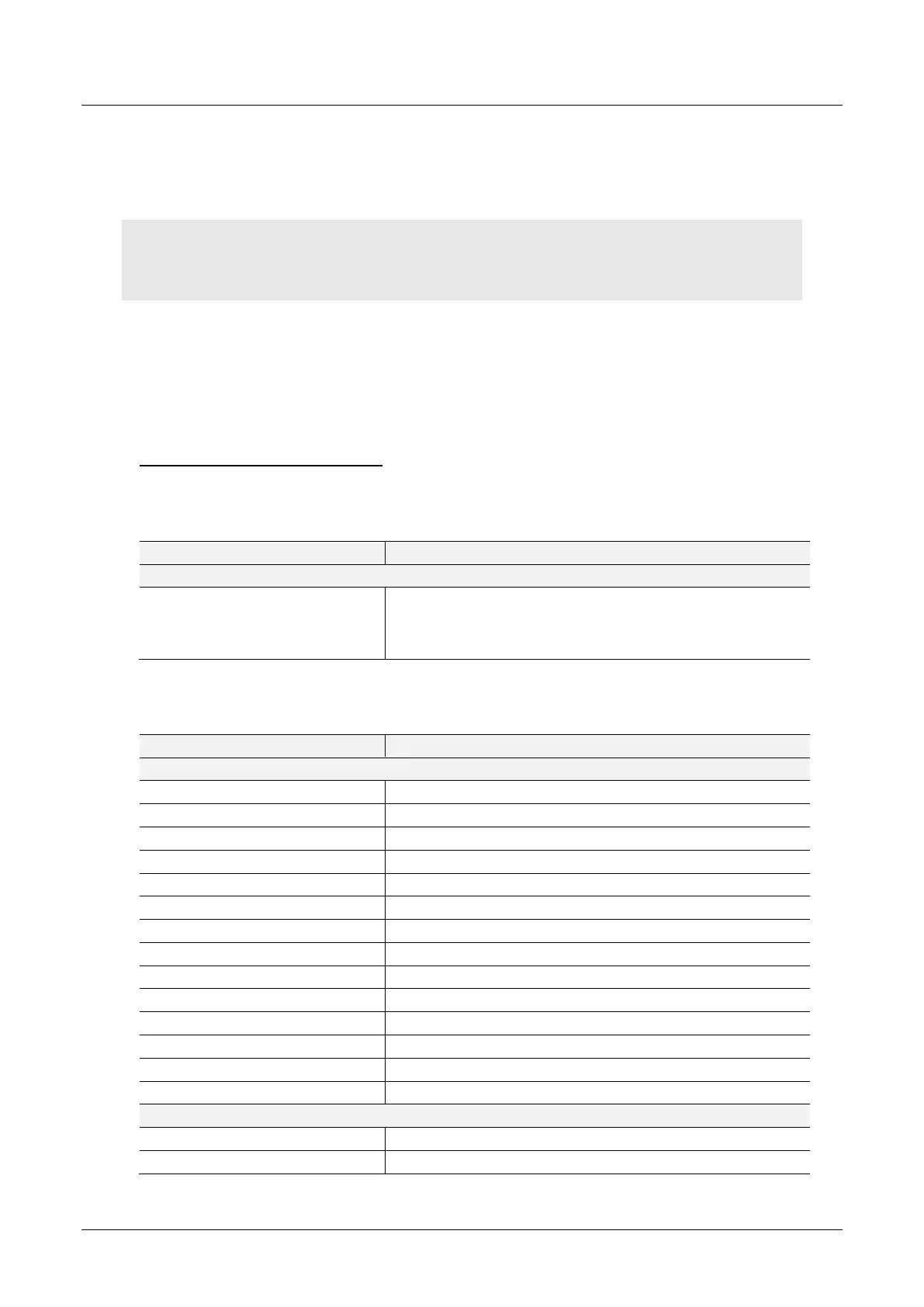
Table 5.42 – Modbus Master Control
0 - Set PROFIBUS OFFLINE
1 - Set PROFIBUS STOP
2 - Set PROFIBUS CLEAR
3 - Set PROFIBUS OPERATIONAL
The Master and Slave Status is populated in either Coil (CS) or Holding (HR)
registers starting at the Status Register offset.
Table 5.43 – Modbus Master and Device Status
Master/Slave Mode (1 = Slave Mode)
Live List Flags (Station Address 0 - 126)
Data Exchange Flags (Station Address 0 - 126)
Alarm Pending Flags (Station Address 0 - 126)
Diagnostic Pending Flags (Station Address 0 - 126)
544 + (16 x [Station Address])
545 + (16 x [Station Address])