PLX51-PBM Setup
PROFIBUS DPV0/DPV1 Master or Slave to EtherNet/IP™ or Modbus® Gateway User Manual
ProSoft Technology, Inc. Page 34 of 196
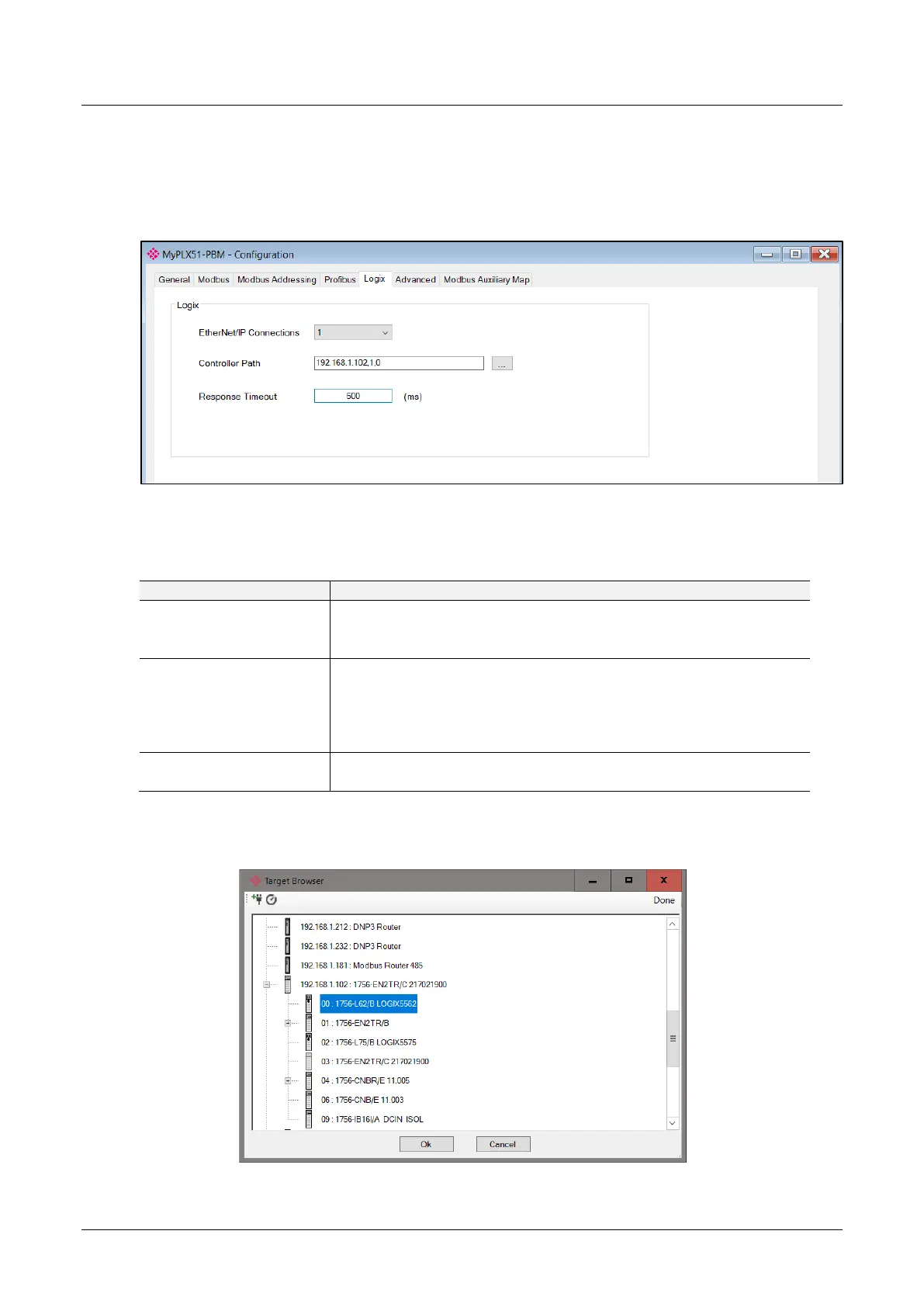
3.5.6 Logix
The Logix configuration is shown in the figure below. It is only relevant when the
Primary Interface is set to EtherNet/IP.
The PLX51-PBM Logix configuration window is opened by either double clicking on
the module in the tree or right-clicking the module and selecting Configuration.
Figure 3.25 – PLX51-PBM Logix configuration
The Logix configuration consists of the following parameters:
Table 3.6 - Logix configuration parameters
The number of EtherNet/IP (CIP) Connections to be used in the exchange
with Logix (1 to 4).
Note, this value must match that configured in the Logix IO tree.
This is the CIP path to the Logix controller.
In PROFIBUS Slave Mode, this path will be used for the Class 3 data
exchanges for DPV1 objects and alarms.
Note: This path can be either entered manually, or configured using the
Target Browser.
The maximum time (ms) allowed for a Class 3 response from the Logix
controller.
To browse to a controller path, select the Browse (“…”) button to open the Target
Browser. Then select a Logix controller and select Ok. The path will then be updated
automatically.
Figure 3.26 – Target Browser – Selecting Logix controller