PLX51-PBM Setup
PROFIBUS DPV0/DPV1 Master or Slave to EtherNet/IP™ or Modbus® Gateway User Manual
ProSoft Technology, Inc. Page 27 of 196
3.5.2 Modbus
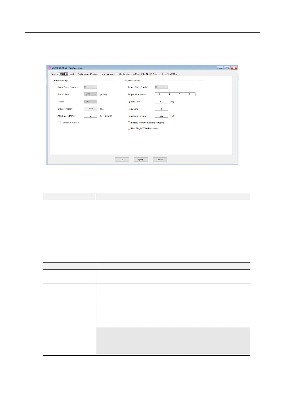
The Modbus configuration is shown in the figure below. The PLX51-PBM Modbus
configuration window is opened by either double clicking on the module in the tree or
right-clicking the module and selecting Configuration.
Figure 3.20 – PLX51-PBM Modbus configuration
The Modbus configuration consists of the following parameters:
Table 3.2 - Modbus configuration parameters
The Modbus Node Number that will be used when the PLX51-PBM is in the
Stand-alone Master mode and a Modbus Slave.
When the Primary Interface is set to Modbus RTU (232/485) then this setting
is the BAUD Rate over the serial communication.
When the Primary Interface is set to Modbus RTU (232/485) then this setting
is the Parity over the serial communication.
The slave timeout time in milliseconds.
The TCP port to be used for the Modbus communication can be configured. If
a zero is entered, the module will use the standard TCP port 502.
Enables the on-board 124Ω RS485 terminating resistor.
The remote Modbus node to poll. (Modbus Master only)
The remote Modbus IP Address to poll. (Modbus TCP Master only)
The period (in milliseconds) between master requests to the target Modbus
device. (Modbus Master only)
The number of successive Modbus request retries (Modbus Master only)
The time (in milliseconds) the module will wait for a Modbus response
(Modbus Master only)
Enable Modbus Auxiliary
Mapping
When this is enabled the PLX51-PBM will be able to read from, and write to,
multiple Modbus Slaves by using the Modbus Auxiliary Map tab.
IMPORTANT: When Modbus Auxiliary Mapping is enabled, the automatic polling of
referenced Modbus registers is disabled. It is the user’s responsibility to ensure that all the
required Profibus control and data registers are collected from the appropriate remote Modbus
slave devices.