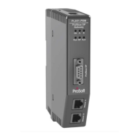
PLX51-PBM Operation
PROFIBUS DPV0/DPV1 Master or Slave to EtherNet/IP™ or Modbus® Gateway User Manual
ProSoft Technology, Inc. Page 135 of 196
5.2.2 PROFIBUS DP - Slave
The PLX51-PBM in Slave mode will operate similar to when in Master mode, but
each configured Slave will be enabled by setting the correct enable bit in the Device
Control Register. Once the respective bit has been set in the Device Control Register
the PLX51-PBM Slave will become “alive” on the PROFIBUS network and will start
responding to a PROFIBUS DP Master.
Slave Device Status
The Slave Status is populated in Coil (CS) or Holding (HR) registers starting at the
Status Register offset.
Table 5.52 – Modbus Master and Device Status
Master/Slave Mode (1 = Slave Mode)
Live List Flags (Station Address 0 - 126)
Data Exchange Flags (Station Address 0 - 126)
Alarm Pending Flags (Station Address 0 - 126)
Diagnostic Pending Flags (Station Address 0 - 126)
544 + (16 x [Station Address])
545 + (16 x [Station Address])
546 + (16 x [Station Address])
547 + (16 x [Station Address])
Disabled by Output Assembly
548 + (16 x [Station Address])
549 + (16 x [Station Address])
550 + (16 x [Station Address])
551 + (16 x [Station Address])
Output Assembly Station Address Mismatch
552 + (16 x [Station Address])
553 + (16 x [Station Address])
554 + (16 x [Station Address])
The Slave Device Enable and (Alarm) Control is located in Coil (CS) or Holding (HR)
registers starting at the Device Control Register offset.
Table 5.53 – Modbus Slave Device Control
Device Enable (Station Address 0 - 126)
128 + (8 x [Station Address])

 Loading...