EasyManuals Logo

ProSoft Technology PLX51-PBM User Manual

ProSoft Technology PLX51-PBM
196 pages
To Next Page IconTo Next Page
To Previous Page IconTo Previous Page
Page #16 background imageLoading...
Page #16 background image
PLX51-PBM Installation
PROFIBUS DPV0/DPV1 Master or Slave to EtherNet/IP™ or Modbus® Gateway User Manual
ProSoft Technology, Inc. Page 16 of 196
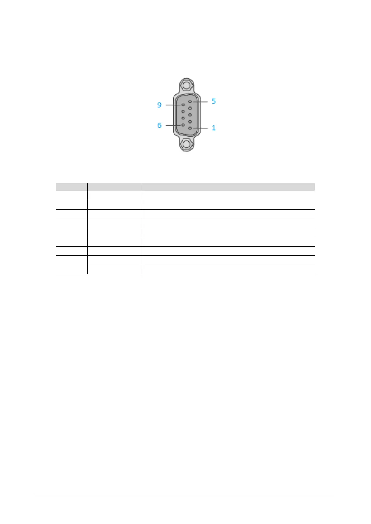
2.3 PROFIBUS DP Port (RS485)
The PROFIBUS DP port uses a female DB9 connector. This provides connection for
the communication conductors, cable shielding and +5Vdc output power.
Figure 2.7 PLX51-PBM PROFIBUS DP (RS485) DB9 connector
Table 2.2 DB 9 Connector layout
Pin
Signal
Description
1
-
Not connected
2
-
Not connected
3
RxD/TxD-P
Data received and transmit (+)
4
CNTR-P
Control signal to repeater (+)
5
DGND
Reference potential for +5Vdc
6
VP
+5Vdc for terminating resistors (active termination)
7
-
Not connected
8
RxD/TxD-N
Data received and transmit (-)
9
-
Not connected

Table of Contents

Questions and Answers:

Question and Answer IconNeed help?

Do you have a question about the ProSoft Technology PLX51-PBM and is the answer not in the manual?

ProSoft Technology PLX51-PBM Specifications

General IconGeneral
BrandProSoft Technology
ModelPLX51-PBM
CategoryGateway
LanguageEnglish

Related product manuals