PLX51-PBM Operation
PROFIBUS DPV0/DPV1 Master or Slave to EtherNet/IP™ or Modbus® Gateway User Manual
ProSoft Technology, Inc. Page 139 of 196
When the PROFIBUS Master acknowledges the alarm, the SlaveAlarmAck bit will be
set, indicating that the next alarm can be triggered.
Table 5.56 – Modbus Device Status
544 + (16 x [Station Address])
545 + (16 x [Station Address])
546 + (16 x [Station Address])
547 + (16 x [Station Address])
Disabled by Output Assembly
548 + (16 x [Station Address])
549 + (16 x [Station Address])
550 + (16 x [Station Address])
551 + (16 x [Station Address])
Output Assembly Station Address Mismatch
552 + (16 x [Station Address])
553 + (16 x [Station Address])
554 + (16 x [Station Address])
NOTE: An alarm is triggered when the Alarm Trigger bit toggles from 0 to 1.
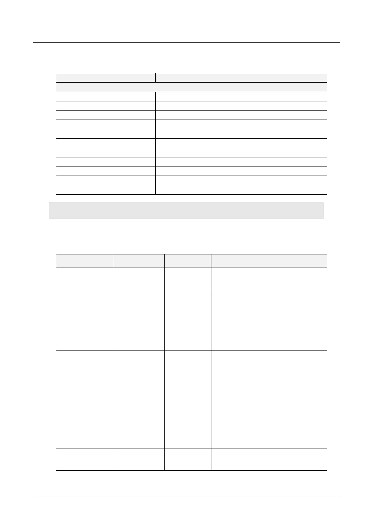
The format of the DPV1 Alarm data in the Modbus Holding Register array is shown
below:
Table 5.57 – Slave Alarm Data Format
Length of the Alarm Data in bytes. See
appendix for the definitions of the returned
status.
Refer to the PROFIBUS Specification EN
50170 for information regarding the
diagnostics.
Below are some examples:
1 - Diagnosis_Alarm
3 - Pull_Alarm
4 - Plug_Alarm
Refer to the PROFIBUS Specification EN
50170 for information regarding the
diagnostics.
Refer to the PROFIBUS Specification EN
50170 for information regarding the
diagnostics.
Below are some examples:
0 - no further differentiation
1 – Incident appeared
2 – Incident disappeared and slot is ok
3 - One incident disappeared, others
remain
Refer to the PROFIBUS Specification EN
50170 for information regarding the
diagnostics.