PLX51-PBM Diagnostics
PROFIBUS DPV0/DPV1 Master or Slave to EtherNet/IP™ or Modbus® Gateway User Manual
ProSoft Technology, Inc. Page 179 of 196
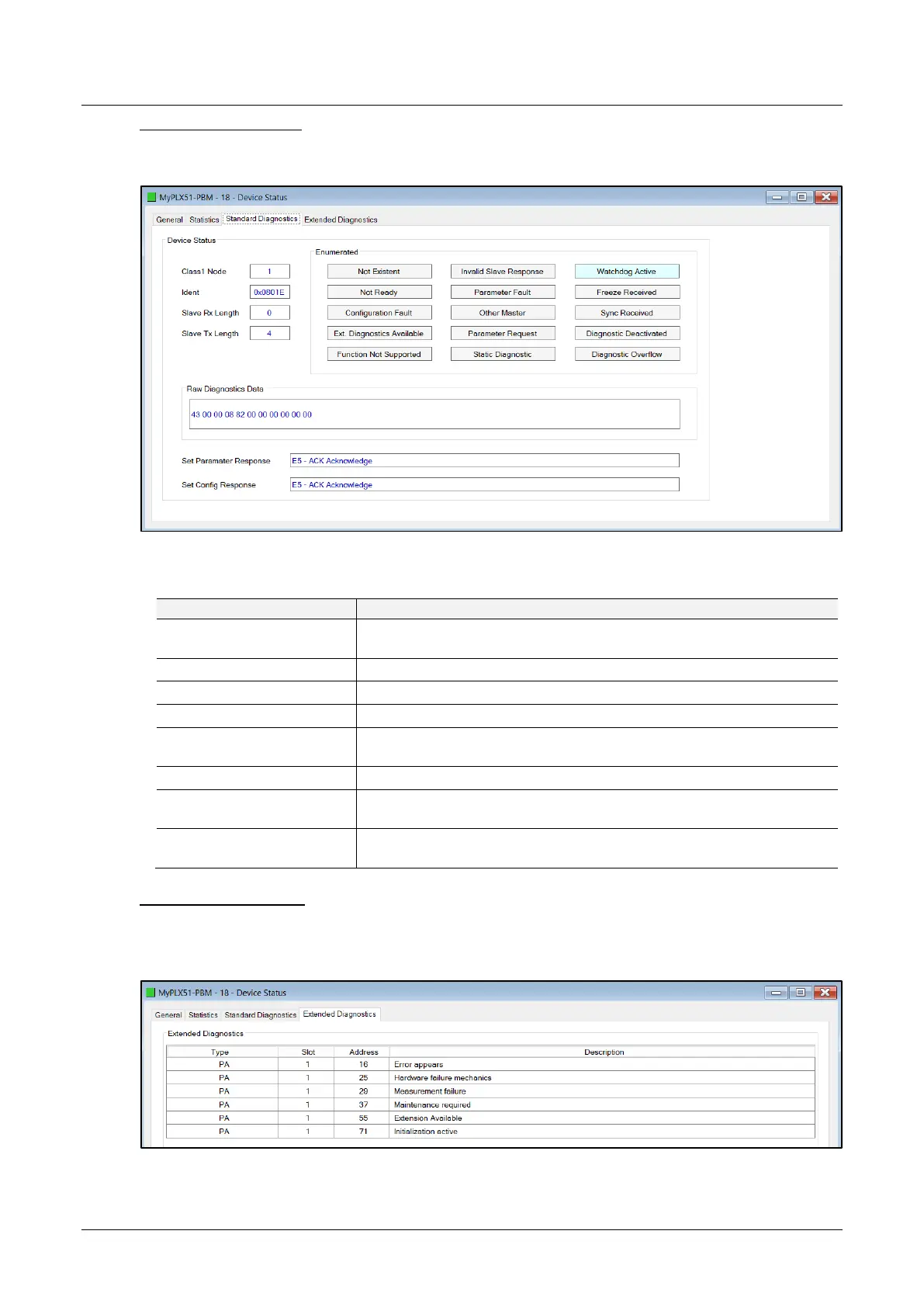
Standard Diagnostics
The Standard Diagnostics (PLX51-PBM Master mode only) tab displays the following
general parameters:
Figure 8.27 – Device Status monitoring – Standard Diagnostics
Table 8.10 - Device Status Monitoring – Standard Diagnostics Tab
The station address of the DP Master that configured the specific device
for DPV0 communication.
The PNO Identification number of the device on the PROFIBUS network.
The number of process data (DPV0) bytes expected from the device.
The number of process data (DPV0) bytes that will be sent to the device.
Refer to the PROFIBUS Specification EN 50170 for information regarding
the diagnostics.
The raw diagnostics in a hexadecimal data string.
This is the last response from the specific field device to the last set
parameter telegram.
This is the last response from the specific field device to the last check
config telegram.
Extended Diagnostics
The Extended Diagnostics (PLX51-PBM Master mode only) are decoded and
displayed in a table form. The diagnostics are decoded using the pre-configured GSD
file.
Figure 8.28 – Device Status monitoring – Extended Diagnostics