Section 3.
Pinspotter Mechanical Operation
400-088-120-02 Page 3-3 Rev. Date: 10/2016
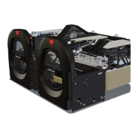
7. Bin and Shuttle Assemblies
The bin (Figure 3-6) stores pins
received from the distributor until
ready for spotting. Two sets of
pins can be stored in the bin
assembly until required.
The shuttle sits just below the bin
and keeps the pins in place until
actuated, at which point it drops
the bottom layer of pins into the
spotting cups.
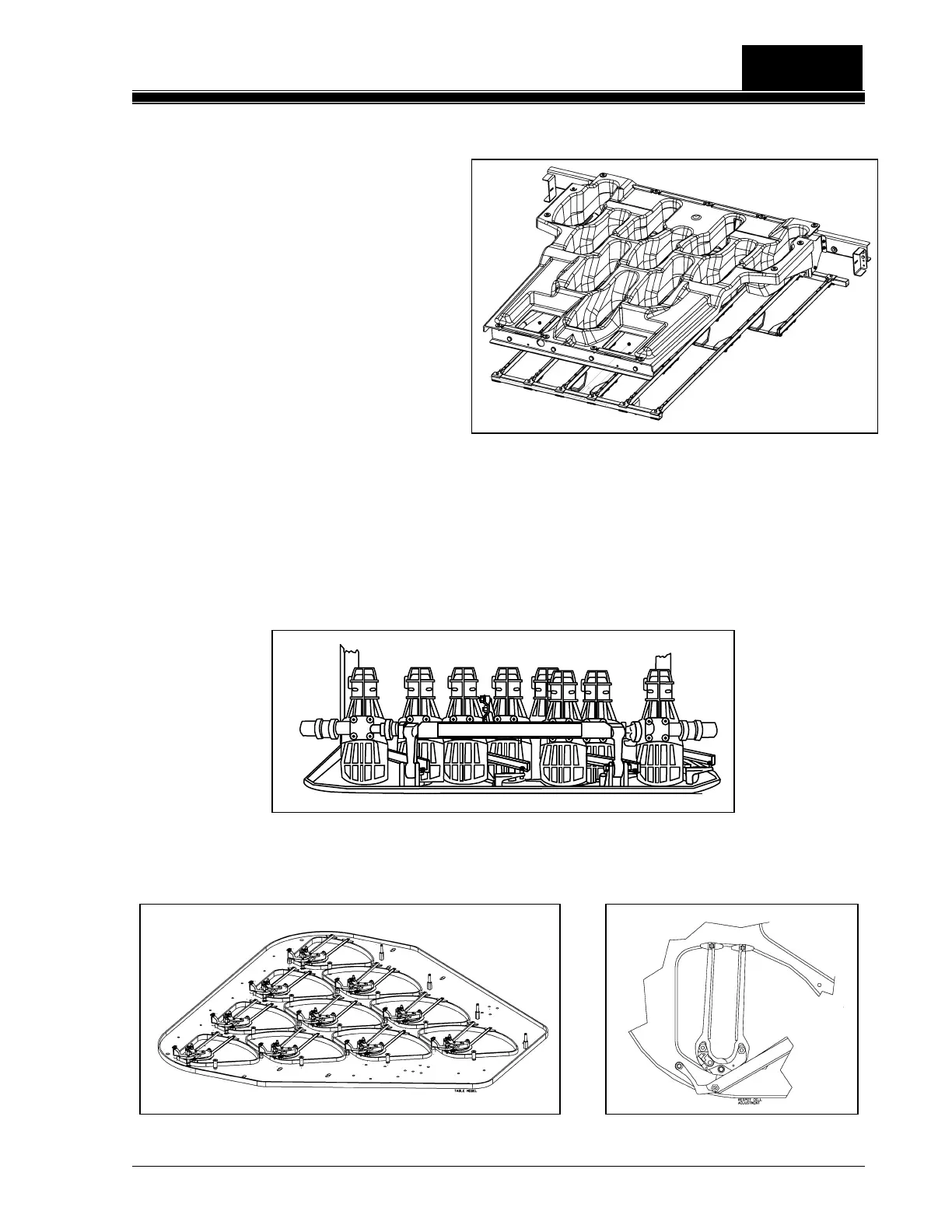
8. Table
The table performs its spotting and respotting functions by employing two major
subassemblies:
The yoke assembly supports the ten spotting cups (Figure 3-7).
The table assembly houses the ten respot cell assemblies (Figures 3-8a & 3-8b).
Figure 3-7, Yoke and Spotting Cups
PULL POWER & MOTOR PLUGS
BEFORE ENTERING MACHINE
Figure 3-6, Bin & Shuttle Assembly
 Loading...