Section 4.2
Machine Adjustments
400-088-120-02 4.2-5 Rev. Date: 10/2016
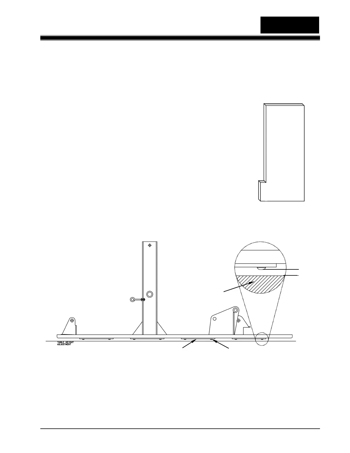
4. Adjust the Table clevis so that the Pinspotter Gauge Tool (Figure 4.3-6), laying flat on the pin
deck, just fits between the pin deck and Button Head Screw in the center of each wing bracket
at the 1, 8 and 10 pin openings resulting in a 5/16-inch gap between the screw head and the pin
deck (see Figure 4.2-7).
a. To adjust the Table height, support the table by placing a solid object
on the pin deck and lowering the table onto it until there is no
tension on the clevis.
b. Remove the clevis bolt, bearing, and spacers.
c. To raise the height of the table, screw the clevis onto the threaded
stud further. This shortens the clevis assembly’s overall length. To
lower the height of the table, lengthen (unscrew) the clevis
assembly. Each half turn of the clevis will result in approximately a
1/8-inch change in table height.
d. Reinstall the bearing, spacers, and clevis bolt.
e. Manually raise the table and remove the support.
f. Lower the table and recheck the table height with the gauge tool.
Figure 4.2-7
5. To obtain the same clearance between the three button head screws and the pin deck proceed
as follows:
 Loading...