Home
Radwin
Radio
2000 C PLUS
Page 160 (Figure 11-10 Site Configuration)
Radwin 2000 C PLUS - Figure 11-10 Site Configuration
297 pages
Manual
Save Page as PDF
To Next Page
To Next Page
To Previous Page
To Previous Page
Loading...
RADWIN
2000
C
Plus
Us
e
r
Manual
Rele
ase
3.5.70
11
‐
11
Configuring
the
GSU
Chapter
11
Site
Configur
ation:
In
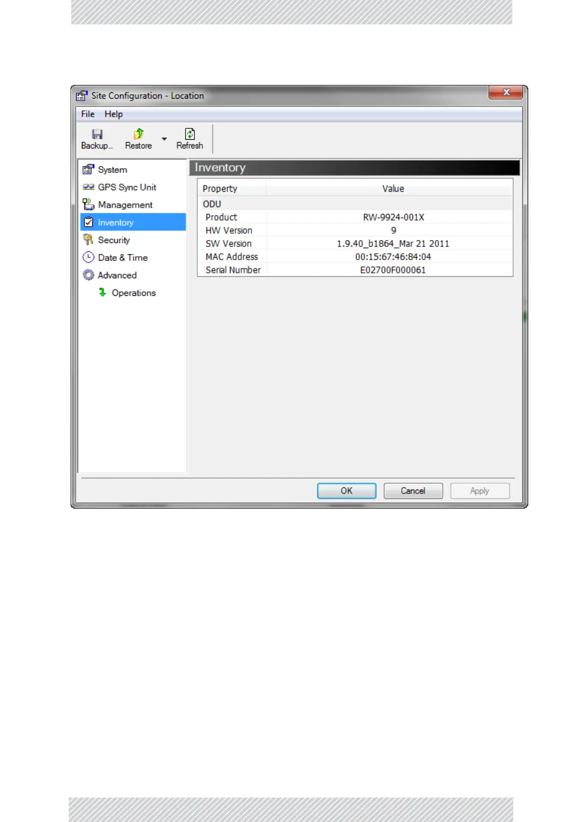
ventory
Fig
ur
e
11
‐
10:
Site
Configur
ation:
Invent
or
y
Site
Configur
ation:
Security
Yo
u
can
only
change
the
SNMP
Community
stri
ng
s:
159
161
Table of Contents
Main Page
Default Chapter
2
Notice
2
RADWIN Worldwide Offices
4
Regulatory Compliance
5
Table of Contents
9
Part 1: Basic Installation
17
Chapter 1: About this User Manual
18
Manual Structure
18
Table 1-1 User Manual - G
18
Terminology
20
Chapter 2: Introduction
22
Welcome to RADWIN 2000 C Plus
22
What's New in Release 3.5.70
22
Key Features of RADWIN 2000 C Plus
22
Components of a RADWIN 2000 C Plus Link
23
Chapter 3: Site Survey
26
Planning the Link Site
26
The Site Survey
26
Stage 1: Preliminary Survey
27
Stage 2: Physical Survey
28
Stage 3: RF Survey
29
RF Planning for Dense Installations and Collocated Sites
29
RF Planning for Dense Installations and Collocated Sites 3
30
Chapter 4: Hardware Installation
31
Overview
31
What's in the Box
32
Odu - Large
32
Figure 4-2 G B E P Oedevice
33
Figure 4-3 Idu-H
34
Figure 4-4 DC Three Pin Power Plug
34
Figure 4-8 External Antennas for Use with Radwin 2000 C Plus
36
Figure 4-11 General Gsu Configuration Using both Ethernet and an Hss Unit
38
Figure 4-13 Using an Ethernet Repeater with Lightning Protectors
39
Tools Required for Installation
39
Safety Practices and Provisions
40
Hardware Installation Workflow for a RADWIN 2000 C Plus Link
41
Figure 4-14 Mounted Odu: Mounted to Awall
43
Figure 4-15 Mounted Odu: Large Angle to Wall
44
Figure 4-16 Mounted Odu: Horizontal Pole
44
Figure 4-17 Flat Panel Antenna Mounting Kit Adapter
45
Figure 4-18 Flat
45
Figure 4-20 Basic Use of Lightning Protectors
48
Figure 4-21 Exposing the Tacky Side of the Sealing Tape
50
Figure 4-22 Start and End Points for Protective - Taping the Unit
50
Figure 4-23 Protecting the Unit Joints with Vinyl Tape
51
Figure 4-24 Mounted and Strapped to the Pole
51
Towards Establishing a Link
53
Getting Started with the RADWIN Manager
54
Installing the RADWIN Manager Application
54
Getting Started with the RADWIN Manager 5
55
Figure 5-1 Pinging the Base Station
56
Figure 5-2 Log - on Window - Default
56
Figure 5-3 Log - on Window Using an Ip Address
57
Figure 5-4 Extended Log - on Window
58
The RADWIN Manager Log-On Concept
58
Figure 5-5 Log on Window Exposing the User Types
59
Log-On Errors and Cautions
60
Table 5-2 User Types , Default
60
Figure 5-6 Unsupported Device Message
61
Figure 5-7 Unreachable Device Message
61
Figure 5-8 Invalid User Type or Password
61
Figure 5-9 Main Window Prior to Link Configuration
62
The Initial RADWIN Manager Main Window
62
What Comes Next
62
Chapter 6: Link Configuration
63
Chapter Contents
63
Link Establishment
63
Figure 6-1 Main Window Prior to Link Configuration
64
Figure 6-2 Main Window : Link Master Odu Ready for Activation
66
Figure 6-3 Main Window : Master Odu Activated , Slave Odu Ready for Registration
74
Figure 6-4 Main Window : Link Master Odu Activated , Slave Odu Registered
75
Figure 6-5 Main Window : Link Fully Operational
77
Exploring the RADWIN Manager Main Window
78
Figure 6-6 Main Tool Bar - Left Three Buttons
78
Figure 6-7 Main Tool Bar - Right Three Buttons
78
Figure 6-8 Sector ( Link ) Status Panel
79
Figure 6-9 Events Log Panel
80
Figure 6-10 Events Log Filter Selection
80
Table 6-1 Link Status Light
81
Table 6-2 Status Line Items
81
Figure 6-11 Link Site Window
82
Figure 6-12 Site Tool Bars
82
Table 6-3 Site Buttons - D
82
Advanced Configuration
83
Figure 6-15 Change or Addb
86
Figure 6-16 Add
87
Figure 6-17 Add Bandsi
90
Figure 6-18 Using the Master
92
Logging on to the Slave ODU over the Air
94
Bulk Software Backup
94
Figure 6-19 Logging on to
94
Figure 6-20 Bulk Backup Setup
95
Figure 6-21 Add / Remove Site
95
Figure 6-22 Adding Asingle
95
Setting RADWIN Manager Preferences
97
Figure 6-23 Monitorp
97
Figure 6-24 Advancedp
99
Configuration with Telnet
100
Figure 6-25 Telnet Session Log
100
Table 6-5 Master Odu Telnet
101
Table 6-6 Master Odu Telnet
101
Figure 6-26 Telnet Management
103
Table 6-8 Slave Odu Telnet
103
Table 6-9 Slave Odu Telnet
103
Chapter 7: Site Configuration
105
Site Tool Bar
105
Figure 7-1 Site Tool Bars
105
Table 7-1 Site Buttons - D
105
Site Configuration Window
106
Figure 7-2 Site Configuration
106
Configuration Tabs
107
Figure 7-3 Site Configuration
107
Figure 7-5 Supported Protocols
113
Figure 7-6 Sector Security
114
Figure 7-7 Change Linkp
115
Figure 7-8 Lost or Forgotten
115
Figure 7-9 Changing Thec
117
Figure 7-10 Alternativec
118
Figure 7-11 Date and Timec
119
Figure 7-12 Change Date and Figure 7-13 Setting Ethernet
119
Figure 7-14 Restore Factory
121
Table 7-2 Enhanced Feature
122
Deactivate Master ODU
123
Deregister Slave ODU
123
Suspend a Deregistered Slave ODU
124
Reset Master ODU, Reset Slave ODU
124
Chapter 8: Operating under the FCC Unrestricted Contention Based Protocol
125
Scope of this Chapter
125
Bringing up a Link
125
Slave ODU Operation
126
Figure 8-1 Air Interface Tab
126
Chapter 9: Monitoring and Diagnostics
127
Retrieving Link Information
127
Table 9-1 Get Diagnosticsd
127
Figure 9-1 Get Diagnostics
128
Throughput Checking
129
Recent Events
130
Performance Monitoring
132
Figure 9-2 Setting the Upper
133
Figure 9-3 Downlink - P
134
Manager Traps
136
Active Alarms
137
Other Diagnostic Aids
138
Part 2: Site Synchronization
139
Chapter 10: Hub Site Synchronization
140
What Is Hub Site Synchronization
140
Figure 10-1 Interference
141
Figure 10-2 Collocated Units
141
Figure 10-3 Collocated Units
141
Hardware Installation
142
Figure 10-6 Hss Sync Signal
144
Figure 10-7 Cascading Two
144
Figure 10-8 Cascading Three
145
ODU/HSS Unit Connection Pinout
146
Radio Frame Pattern (RFP)
146
Figure 10-9 Radio Framep
147
Table 10-2 Radio Framep
147
Table 10-3 Radio Framep
147
Table 10-4 Legend for Radio
147
Link Configuration and HSS
148
Figure 10-11 Setting Them
148
Table 10-5 External Pulses
149
Chapter 11: Using the RADWIN GSU
150
What Is It for
150
GSU Functionality
150
Typical GSU Scenarios
150
GSU Redundancy
152
Figure 11-3 Phase Shifted
152
GSU Kit Contents
153
GSU Installation
154
Figure 11-7 Site Configuration
156
Figure 11-8 Site Configuration
157
Figure 11-9 Site Configuration
159
Figure 11-10 Site Configuration
160
Figure 11-11 Site Configuration
161
Figure 11-12 Setting the Date
162
Figure 11-13 Site Configuration
163
GSU Monitoring and Diagnostics
164
GSU Telnet Support
164
Figure 11-14 Site Configuration
164
Software Upgrade for Gsus
165
Part 3: Advanced Installation Topics
166
Chapter 12: Reserved
167
Chapter 13: VLAN Functionality with RADWIN 2000 C Plus
168
VLAN Tagging - Overview
168
Scope of this Chapter
168
Requirements
168
VLAN Tagging
169
Table 13-1 Port Settings - I
170
VLAN Configuration Using the RADWIN Manager
171
Table 13-2 Port Settings - E
171
Table 13-3 Further Vlan C
174
Chapter 14: False Radar Mitigation Facilities
175
Who Needs It
175
DFS and False Radar Mitigation
175
Configuring False Radar Mitigation
176
Figure 14-1 False Radarm
176
FCC/IC Requirements
177
FCC 5.4Ghz Device Registration
178
Registering the Device
178
TDWR Table
182
Table 15-1 Latitude and Table 16-1 Default Priorities
182
Chapter 16: Quality of Service
184
Prerequisites
184
Terminology
184
Qos - Overview
184
Setting up the Link for Qos
185
Figure 16-1 Q O S Configuration
185
Chapter 17: Reserved
188
Part 4: Field Installation Topics
189
Chapter 18: Link Budget Calculator
190
Overview
190
Calculations
191
About the Fresnel Zone
192
Figure 18-1 Fresnel Zone
193
Running the Link Budget Calculator
194
Figure 18-2 Link Budget
194
Figure 18-4 Band Selector
196
Figure 18-5 Calculation of
197
Figure 18-6 Climacticc F
198
Figure 18-7 Climacticc Factor
199
Figure 18-8 World Map Showing
199
Chapter 19: Spectrum View
201
What Is Spectrum View
201
Who Needs It
201
Scope of this Chapter
201
Two Ways to Run Spectrum View
202
Where Is the Spectrum View Data Stored
202
Spectrum View Main Window
202
Spectrum View Display Function Buttons
204
Running Spectrum View
205
Table 19-1 Spectrum Viewa
205
Figure 19-1 Spectrum Viewa
206
Zooming in and out
207
Chapter 20: Using the Web Interface
208
What Is It for
208
Who Needs It
208
How It Works
208
What It Provides
209
Prerequisites
209
Special Considerations Working with the WI
209
Scope of this Chapter
210
Logging on
210
Figure 20-1 Web Interface - L
211
Site Management - Master ODU
212
Figure 20-2 Web Interface - M
212
Figure 20-3 Link Status Panel
212
Site Management - Slave ODU
218
Part 5: Product Reference
219
Appendix A: Technical Specifications
220
ODU - HBS and HSU
220
Scope of These Specifications
220
Poe Device - Outdoor, DC
226
Gsu
227
Lightning Protector
228
Fast Ethernet CAT-5E Cable Repeater
229
Antenna Characteristics
230
Appendix B: Wiring Specifications
231
ODU-Poe Cable (HBS and HSU
231
HBS/HSS Unit Connection Pinout
232
User Port Connectors
233
DC Power Terminals
233
Table B-4 Fast Ethernetc
233
Table B-5 Terminal Block
233
Appendix C: MIB Reference
234
Introduction
234
Interface API
235
Private MIB Structure
235
Figure C-1 Top Level Sections
236
Figure C-2 Product
236
MIB Parameters
236
Table C-1 Supported Variables
237
Table C-2 Private Mib P
239
Table D-1 Safety Distances
280
Table D-2 Safety Distances
281
AppendixD:RfExposure
282
Appendix E: Setting Antenna Parameters
282
Antenna Issues
282
About Single and Dual Antennas
282
Table - Radwin 2000 C P
284
Considerations for Changing Antenna Parameters
285
Appendix F: Regional Notice: French Canadian
287
Table E-1 Spatial Multiplexing
284
Procédures de Sécurité
287
Figure F-1 Grande Clame
289
Figure F-2 Petite Clame
289
Figure F-3 Bras
289
Installation Sur Pylône Et Mur
289
Montage Sur un
290
Montage Sur un Figure
290
Mib
297
Related product manuals
Radwin 2000 Alpha INT
6 pages
Radwin 5000
252 pages