Instrument Functions
R&S
®
NRP2
123User Manual 1173.9157.02 ─ 03
Within the measurement period, a "fence", i.e. an exclusion interval, can be set. The fence
is defined by its start time and its length. The start time refers to the start of the gate.
In contrast to the numeric "T'gateAv" mode, the definition of fences in the "Gate" mode
is not restricted to the wideband power sensors of the R&S NRP-Z8x series. Instead, all
power sensors are supported that can be operated in "Trace" mode.
Start / Length of Fence
Sets the start time and the length of the fence.
SCPI command:
[SENSe<[1]..4>][:POWer]:TGATe<[1]..4>[:EXCLude]:MID:TIME
on page 273
[SENSe<[1]..4>][:POWer]:TGATe<[1]..4>[:EXCLude]:MID:OFFSet[:
TIME] on page 272
4.5.5 Marker display mode
In the "Marker" mode you can display two markers in addition to the trace(s). The power/
power ratio at the marker positions is displayed together with the marker time. The mark-
ers can be positioned automatically to measure the maximum and minimum power of the
waveform(s). The settings for "Trig"gering, "Filt"ering, "Function", and "Unit" are taken
from the "Trace" display mode and cannot be changed.
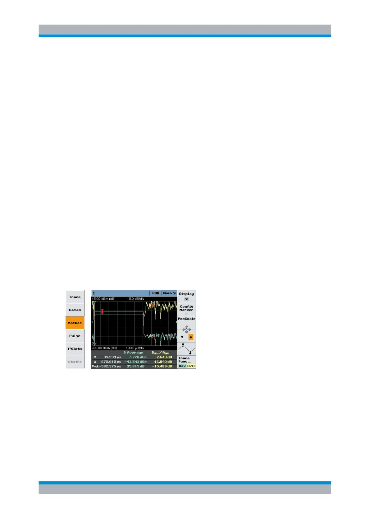
Markers are indicated by red arrows, see figure below.
►
Select "Marker" in the control panel opened via the Window→Graph→"Display" dialog
box ("Trace&Statistics" sensor mode).
Fig. 4-52: Marker display mode
(1st line) = measurement function, display type
▼
= position of first marker and associated power/power ratio
▲
= position of second marker and associated power/power ratio
▼-▲
= time spacing and power ratio of the two markers
Note: The marker positions ▼ and ▲ relate to the delayed trigger event.
Displaying traces