Instrument Functions
R&S
®
NRP2
124User Manual 1173.9157.02 ─ 03
4.5.5.1 Controls in Marker display mode
Display
Selects another view, see chapter 4.5.2, "Trace window", on page 113.
Config Marker...
Opens the subdialog to manually define the marker positions, see chapter 4.5.5.2,
"Marker diagram settings", on page 124.
Pos Scale
Defines if the cursor keys position or scale the waveform.
"Pos"
The cursor keys shift the waveform in horizontal and vertical direction
"Scale"
The cursor keys expand and compress the waveform. When the hori-
zontal scaling is modified, the points (pixels) at the left of the screen
remain unchanged. When the vertical scaling is modified, the neutral
zone depends on the unit selected: the points in the center of the screen
remain unchanged when dBm, dB and dBµV are used. The points at
the bottom of the screen remain unchanged in all other displays.
▼ / ▲
Defines the active marker which can be positioned by means of the cursor keys.
(Max/Min marker position)
Sets the two markers to the extreme values of the selected trace each time the key is
pressed. If two traces are active, pressing the left side of the softkey selects trace 1 and
pressing the right side selcets trace 2.
Trace Func...
Opens the "Trace Function" dialog box, see chapter 4.5.3.4, "Trace function settings",
on page 118 .
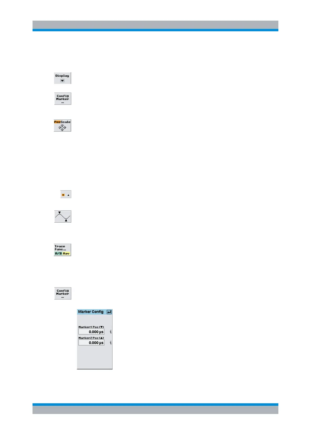
4.5.5.2 Marker diagram settings
►
Open the "Marker Config" dialog box open via the Window→Graph→"Dis-
play"→"Marker" control panel ("Trace&Statistics" sensor mode).
Fig. 4-53: Marker Config dialog box
Displaying traces