Instrument Functions
R&S
®
NRP2
128User Manual 1173.9157.02 ─ 03
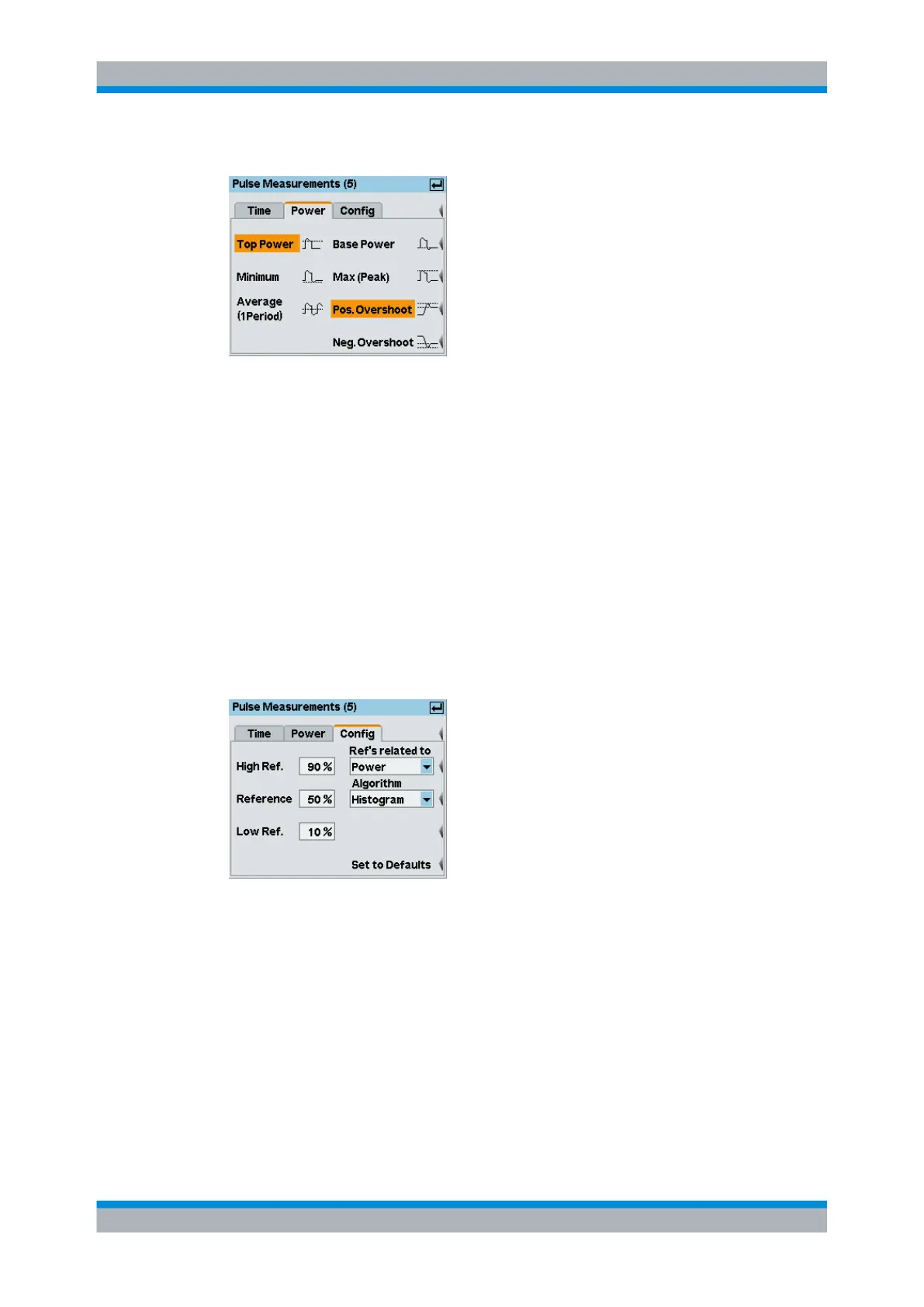
Pulse Measurements / Power
Fig. 4-57: Pulse Measurements / Power tab
The pulse power parameters to be displayed in the info panel are selected on the
"Power" tab.
"Top / Base
Power"
Indication of the power of the pulse top / base, defined in the Pulse
Measurements / Config tab.
"Average (1
period)"
Indication of the average power of the signal. The visible trace length
must exceed one cycle of the waveform. The gate length is arbitrary.
"Max (Peak)"
Indication of the maximum power measured within the analysis window.
"Minimum"
Indication of the minimum power measured within the analysis window.
"Pos. / Neg.
Overshoot"
Indicates the relative amount of positive / negative overshoot. The indi-
cates value depends on the "Related to" (Power / Voltage) setting in the
pulse measurement "Config" menu.
Pulse Measurements / Config
Fig. 4-58: Pulse Measurements / Config tab
The "Config" tab contains the threshold parameters to define the high, mid and low ref-
erence levels which are used to determine the pulse timing. All values are specified in
percent of the pulse amplitude, either expressed in terms of power (Watt) or voltage (Volt).
"Low Ref."
The "Low Ref." level defines the start of the rising edge and the end of
the falling edge of the pulse, needed for measurement of the rise / fall
time.
"High Ref."
The "High Ref." level defines the end of the rising edge and the start of
the falling edge of the pulse, needed for measurement of the rise / fall
time.
Displaying traces