RL78/F13, F14 CHAPTER 19 DTC
R01UH0368EJ0210 Rev.2.10 1436
Dec 10, 2015
19.2.4 Peripheral enable register 1 (PER1)
The PER1 register is used to enable or disable supplying the clock to the peripheral hardware. Clock supply to the
hardware that is not used is also stopped so as to decrease the power consumption and noise.
When using the DTC, be sure to set bit 3 (DTCEN) to 1.
The PER1 register can be set by a 1-bit or 8-bit memory manipulation instruction.
Reset signal generation clears this register to 00H.
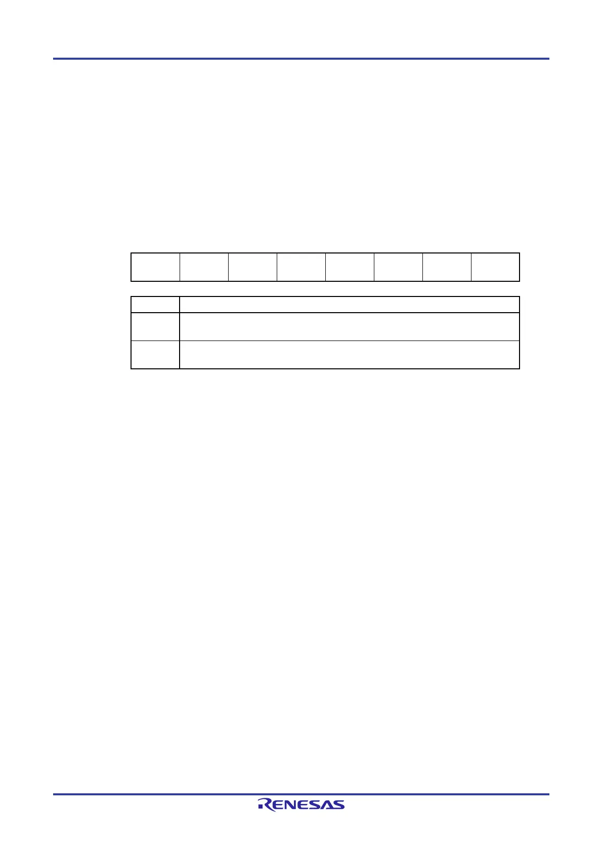
Figure 19-4. Format of Peripheral Enable Register 1 (PER1)
Address: F02C0H After reset: 00H R/W
Symbol <7> 6 <5> <4> <3> 2 1 <0>
PER1
DACEN
Note 1
0
CMPEN
Note 1
TRD0EN
Note 2
DTCEN 0 0 TRJ0EN
DTCEN Control of DTC input clock supply
0
Stops input clock supply.
DTC cannot run.
1
Enables input clock supply.
DTC can run.
Note 1. Only in RL78/F14.
2. When FRQSEL4 = 1 in the user option byte (000C2H/020C2H), set f
CLK to fIH before setting the
bit 4 (TRD0EN) of the peripheral enable register 1 (PER1). When changing fCLK to a clock
other than fIH, clear the bit 4 (TRD0EN) of the peripheral enable register 1 (PER1) before
changing.
Caution Be sure to clear the following bits to 0.
RL78/F13: bits 1, 2, 5, 6, and 7
RL78/F14: bits 1, 2, and 6
 Loading...


