RL78/F13, F14 CHAPTER 15 SERIAL ARRAY UNIT
R01UH0368EJ0210 Rev.2.10 815
Dec 10, 2015
15.3.8 Serial channel start register m (SSm)
The SSm register is a trigger register that is used to enable starting communication/count by each channel.
When 1 is written a bit of this register (SSmn), the corresponding bit (SEmn) of serial channel enable status register
m (SEm) is set to 1 (Operation is enabled). Because the SSmn bit is a trigger bit, it is cleared immediately when
SEmn = 1.
Set the SSm register by a 16-bit memory manipulation instruction.
Set the lower 8 bits of the SSm register with an 1-bit or 8-bit memory manipulation instruction with SSmL.
Reset signal generation clears the SSm register to 0000H.
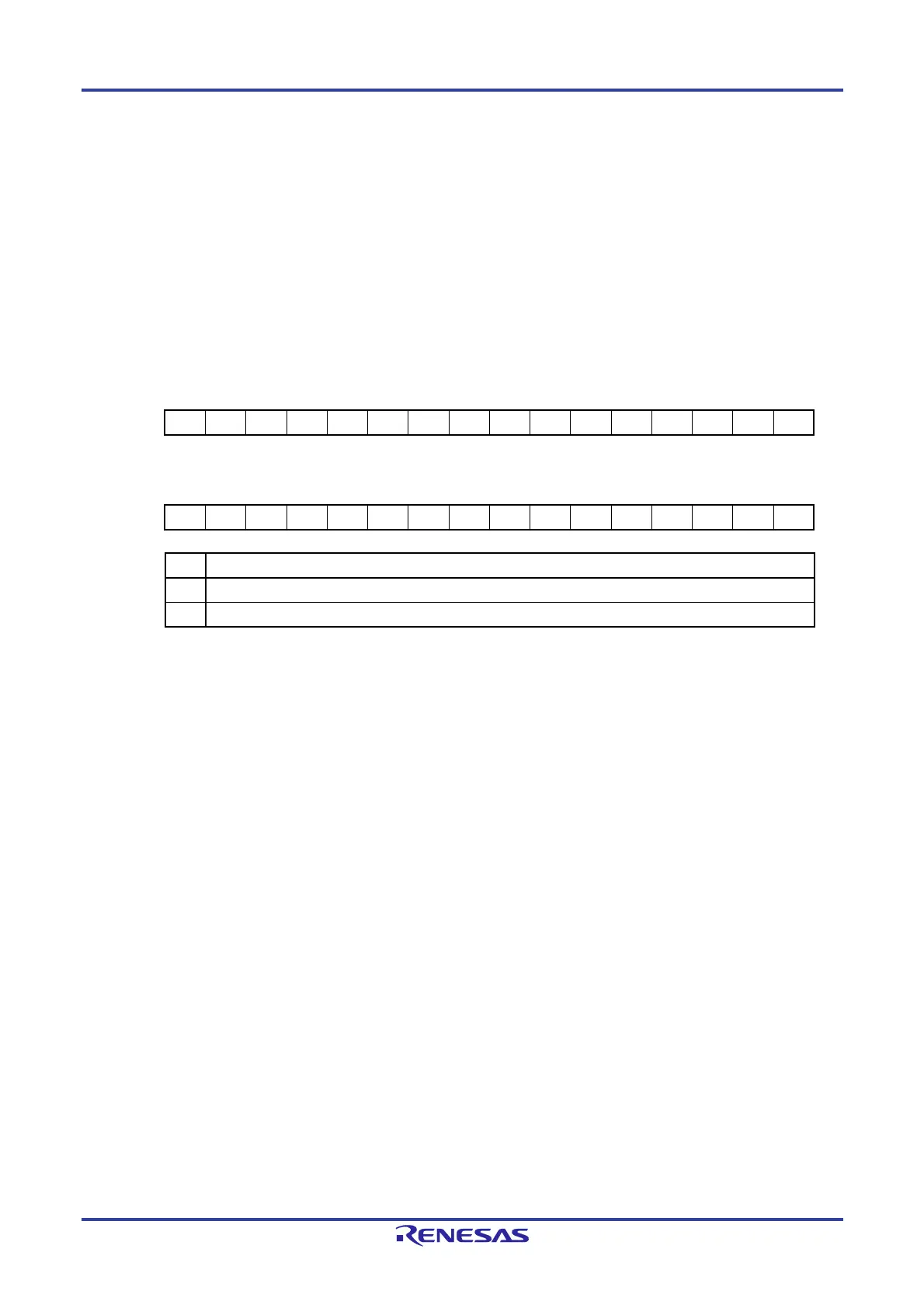
Figure 15-11. Format of Serial Channel Start Register m (SSm)
Address: F0112H, F0113H (SS0) After reset: 0000H R/W
Symbol 15 14 13 12 11 10 9 8 7 6 5 4 3 2 1 0
SS0 0 0 0 0 0 0 0 0 0 0 0 0 0 0 SS01 SS00
Address: F0152H, F0153H (SS1) After reset: 0000H R/W
Symbol 15 14 13 12 11 10 9 8 7 6 5 4 3 2 1 0
SS1 0 0 0 0 0 0 0 0 0 0 0 0 0 0 SS11 SS10
SSmn Operation start trigger of channel n
0 No trigger operation
1 Sets the SEmn bit to 1 and enters the communication wait status
Note
.
Note If a communication operation is already under execution, the operation is stopped.
The value of the control register and shift register, and the status of the serial clock I/O pin, serial data output
pin, and each error flag (FEFmn: framing error flag, PEFmn: parity error flag, OVFmn: overrun error flag) are
held.
Cautions 1. Be sure to clear bits 15 to 2 of the SS0 register and bits 15 to 2 of the SS1 register to 0.
2. For the UART reception, set the RXEmn bit of SCRmn register to 1, and then be sure to set
SSmn to 1 after 4 or more f
MCK clocks have elapsed.
Remarks 1. m: Unit number (m = 0, 1), n: Channel number (n = 0, 1)
2. When the SSm register is read, 0000H is always read.

 Loading...


