RL78/F13, F14 CHAPTER 15 SERIAL ARRAY UNIT
R01UH0368EJ0210 Rev.2.10 807
Dec 10, 2015
15.3.4 Serial communication operation setting register mn (SCRmn)
The SCRmn register is a communication operation setting register of channel n. It is used to set a data
transmission/reception mode, phase of data and clock, whether an error signal is to be masked or not, parity bit, start
bit, stop bit, and data length.
Rewriting the SCRmn register is prohibited when the register is in operation (when SEmn = 1).
Set the SCRmn register by a 16-bit memory manipulation instruction.
Reset signal generation sets the SCRmn register to 0087H.
Figure 15-7. Format of Serial Communication Operation Setting Register mn (SCRmn) (1/3)
Address: F010CH, F010DH (SCR00), F010EH, F010FH (SCR01), After reset: 0087H R/W
F014CH, F014DH (SCR10), F014EH, F014FH (SCR11)
Symbol 15 14 13 12 11 10 9 8 7 6 5 4 3 2 1 0
SCRmn
TXE
mn
RXE
mn
DAP
mn
CKP
mn
0 0
PTC
mn1
PTC
mn0
DIR
mn
0
SLC
mn1
SLC
mn0
DLS
mn3
DLS
mn2
DLS
mn1
DLS
mn0
TXE
mn
RXE
mn
Setting of operation mode of channel n
0 0 Disable communication.
0 1 Reception only
1 0 Transmission only
1 1 Transmission/reception
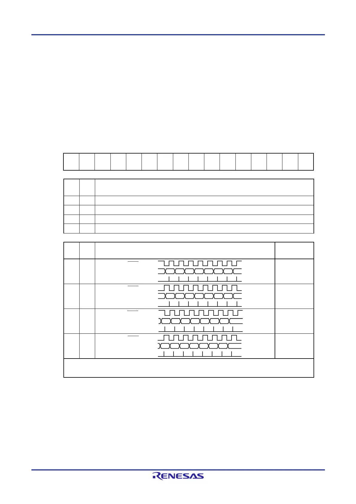
DAP
mn
CKP
mn
Selection of data and clock phase in CSI mode Type
0 0
1
0 1
2
1 0
3
1 1
4
Be sure to set DAPmn, CKPmn = 0, 0 in the UART mode and simplified I
2
C mode.
Set CKPmn to 1, when SSEmn = 1 (Enables SSImn
___________
pin input).
Caution Be sure to clear bits 6, 10, and 11 to 0.
Remark m: Unit number (m = 0, 1), n: Channel number (n = 0, 1), p: CSI number (p = 00, 01, 10, 11)
D7 D6 D5 D4 D3 D2 D1 D0
SCKp
SOp
SI
p
input timing
D7 D6 D5 D4 D3 D2 D1 D0
SCKp
SOp
SI
p input timing
D7 D6 D5 D4 D3 D2 D1 D0
SCKp
SOp
SI
p
input timing
D7 D6 D5 D4 D3 D2 D1 D0
SCKp
SOp
SI
p
input timing
 Loading...


