RL78/F13, F14 CHAPTER 19 DTC
R01UH0368EJ0210 Rev.2.10 1437
Dec 10, 2015
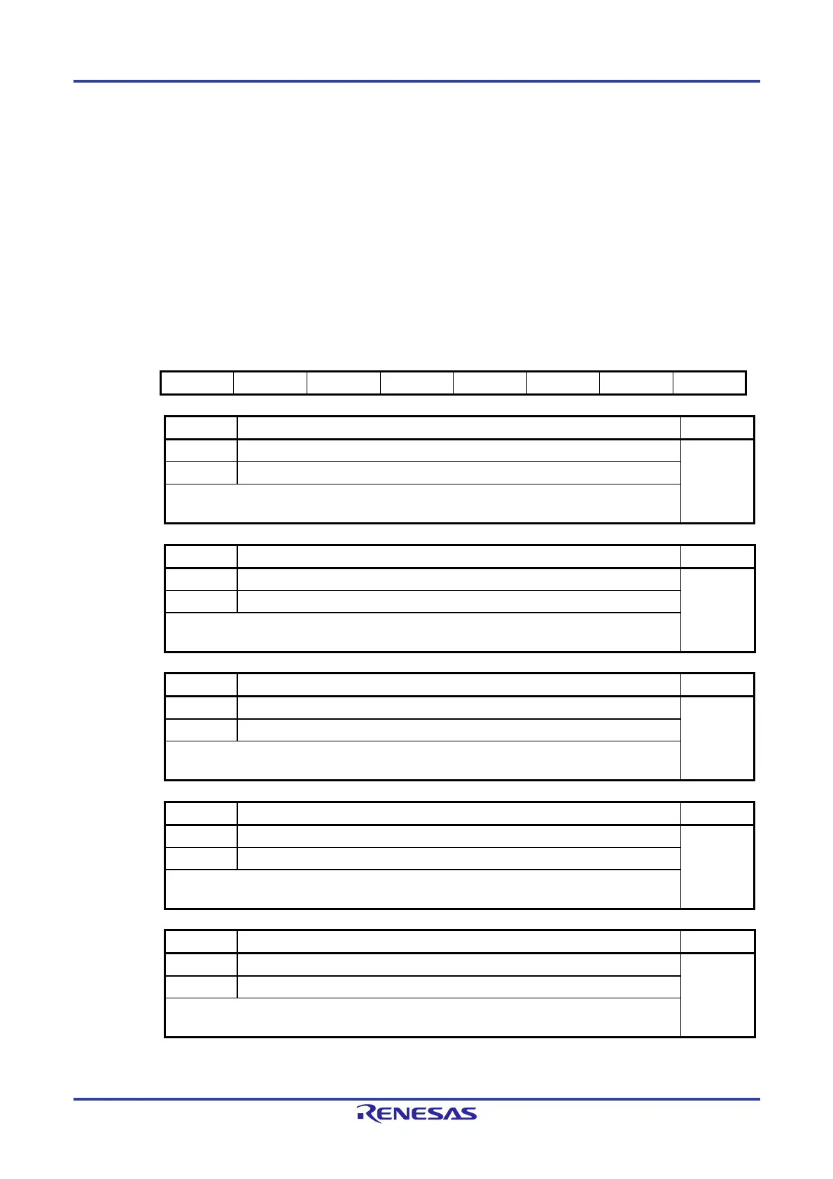
19.2.5 DTC Activation Enable Register i (DTCENi) (i = 0 to 5)
This is an 8-bit register which enables or disables DTC activation by interrupt sources. Table 19-6 lists the
correspondence between interrupt sources and bits DTCENi0 to DTCENi7.
Set the DTCENi register by an 8-bit or 1-bit memory manipulation instruction.
Notes 1. Modify bits DTCENi0 to DTCENi7 if an activation source corresponding to the bit has not been generated.
2. Do not access the DTCENi register using a DTC transfer.
Figure 19-5. DTC Activation Enable Register i (DTCENi) (i = 0 to 5)
Address: F02E8H (DTCEN0), F02E9H (DTCEN1), F02EAH (DTCEN2), After reset: 00H
F02EBH (DTCEN3), F02ECH (DTCEN4), F02EDH (DTCEN5)
Note
Symbol <7> <6> <5> <4> <3> <2> <1> <0>
DTCENi DTCENi7 DTCENi6 DTCENi5 DTCENi4 DTCENi3 DTCENi2 DTCENi1 DTCENi0
DTCENi7 DTC activation enable i7 R/W
0 Activation disabled R/W
1 Activation enabled
The DTCENi7 bit is set to 0 (activation disabled) by a condition for generating a transfer end
interrupt.
DTCENi6 DTC activation enable i6 R/W
0 Activation disabled R/W
1 Activation enabled
The DTCENi6 bit is set to 0 (activation disabled) by a condition for generating a transfer end
interrupt.
DTCENi5 DTC activation enable i5 R/W
0 Activation disabled R/W
1 Activation enabled
The DTCENi5 bit is set to 0 (activation disabled) by a condition for generating a transfer end
interrupt.
DTCENi4 DTC activation enable i4 R/W
0 Activation disabled R/W
1 Activation enabled
The DTCENi4 bit is set to 0 (activation disabled) by a condition for generating a transfer end
interrupt.
DTCENi3 DTC activation enable i3 R/W
0 Activation disabled R/W
1 Activation enabled
The DTCENi3 bit is set to 0 (activation disabled) by a condition for generating a transfer end
interrupt.
(Note is listed on the next page.)
 Loading...


