RL78/F13, F14 CHAPTER 14 COMPARATOR (RL78/F14 Only)
R01UH0368EJ0210 Rev.2.10 782
Dec 10, 2015
4. Wait for the input switching stabilization wait time (300 ns)
5. Set bit COE in CMPCTL register to 1.
6. Clear flag bit CMPIF0 in the control register.
4. Be sure to set bit 7 to 0.
14.2.4 Comparator Output Monitor Register (CMPMON)
This register is used to monitor the comparator output.
The CMPMON register can be set by a 1-bit or 8-bit memory manipulation instruction.
Reset signal generation sets this register to 00H.
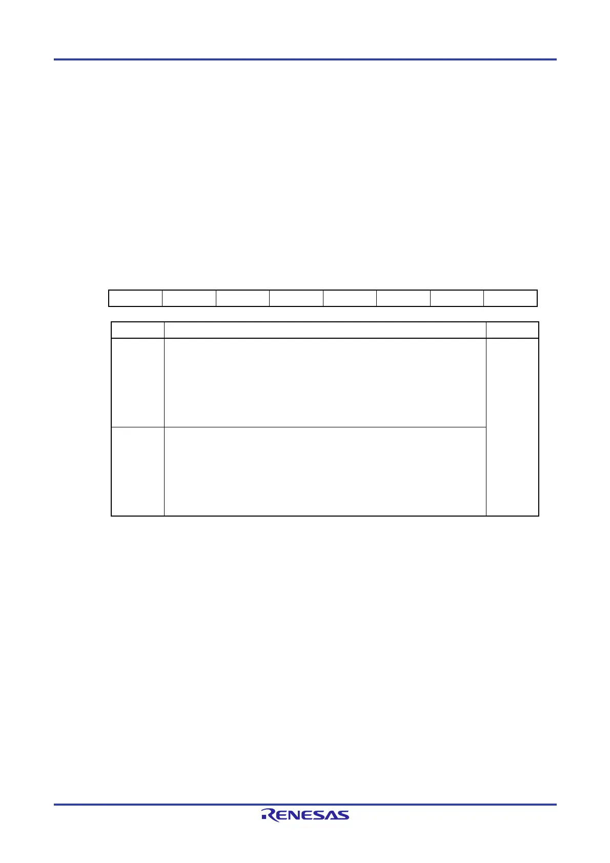
Figure 14-5. Format of Comparator Output Monitor Register (CMPMON)
Address: F02A2H After reset: 00H
Symbol 7 6 5 4 3 2 1 0
CMPMON 0 0 0 0 0 0 0 CMPMON0
CMPMON0 Comparator output monitor value R/W
0 When CINV = 0 (comparator output is not inverted)
Comparator input voltage (IVCMP0n) < reference voltage
Comparator operation disabled (HCMPON = 0)
Comparator output is disabled (COE = 0)
When CINV = 1 (converter output is inverted)
Comparator input voltage (IVCMP0n) > reference voltage
R/W
1 When CINV = 0 (comparator output is not inverted)
Comparator input voltage (IVCMP0n) > reference voltage
When CINV = 1 (comparator output is inverted)
Comparator input voltage (IVCMP0n) < reference voltage
Comparator operation disabled (HCMPON = 0)
Comparator output is disabled (COE = 0)
Cautions 1. When comparator operation is enabled (HCMPON = COE = 1) but the noise filter is not in
use (CDFS1 and CDFS0 = 00B), write the software so that the CMPMON0 bit is read twice
and the values are only used after the two consecutive values match.
2. Be sure to set bits 7 to 1 to 0.
 Loading...


