RL78/F13, F14 CHAPTER 5 CLOCK GENERATOR
R01UH0368EJ0210 Rev.2.10 393
Dec 10, 2015
5.3.14 PLL Status Register (PLLSTS)
This register is used to indicate the operation status of the PLL clock.
Read the PLLSTS register by a 1-bit or 8-bit memory manipulation instruction.
Reset signal generation sets this register to 00H.
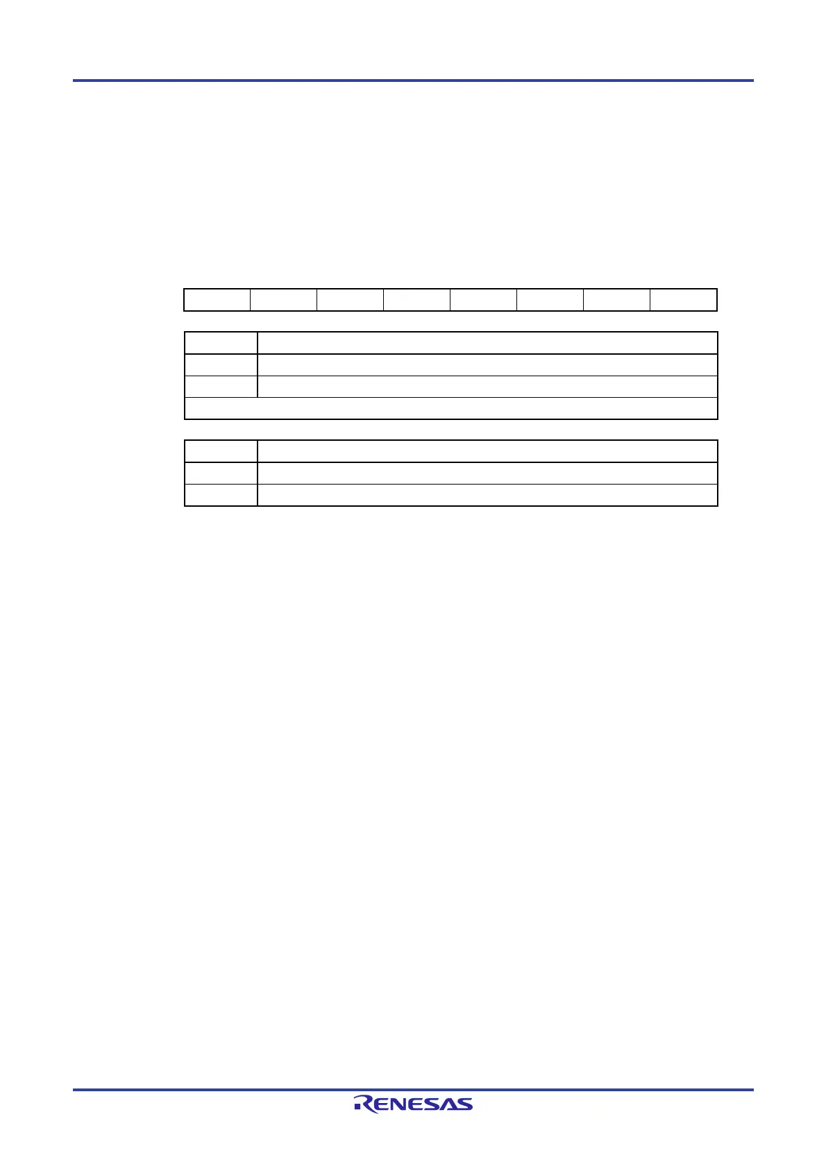
Figure 5-21. Format of PLL Status Register (PLLSTS)
Address: F02C6H After reset: 00H R
Symbol <7> 6 5 4 <3> 2 1 0
PLLSTS LOCK 0 0
0
SELPLLS 0 0 0
LOCK PLL locked state
0 Unlocked state
1
Note
Locked state
This bit is set to 1 when the lock-up wait counter overflows.
SELPLLS CLock mode state
0 Clock through mode (fMAIN)
1 PLL-clock-selected mode (fPLL)
Note When PLL operation starts, a wait time for the PLL to be locked (LOCK = 1) is required.
 Loading...


