RL78/F13, F14 CHAPTER 6 TIMER ARRAY UNIT
R01UH0368EJ0210 Rev.2.10 540
Dec 10, 2015
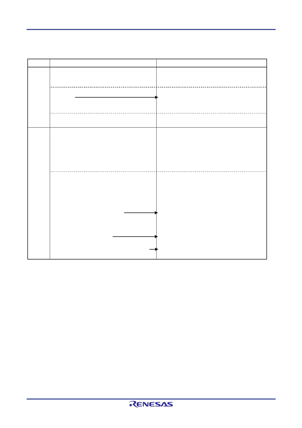
Figure 6-81. Operation Procedure When Multiple PWM Output Function Is Used (output two types of PWMs)
(1/2)
Software Operation Hardware Status
TAU
default
setting
Power-off status
(Clock supply is stopped and writing to each register is
disabled.)
Sets the TAUmEN bit of peripheral enable register 0
(PER0) to 1.
Power-on status. Each channel stops operating.
(Clock supply is started and writing to each register is
enabled.)
Sets timer clock select register m (TPSm).
Determines clock frequencies of CKm0 to CKm3.
Channel
default
setting
Sets timer mode registers mn, mp, mq (TMRmn,
TMRmp, TMRmq) of each channel to be used
(determines operation mode of channels).
An interval (period) value is set to timer data register mn
(TDRmn) of the master channel, and a duty factor is set
to the TDRmp and TDRmq registers of the slave
channels.
Channel stops operating.
(Clock is supplied and some power is consumed.)
Sets slave channels.
The TOMmp and TOMmq bits of timer output mode
register m (TOMm) are set to 1 (slave channel output
mode).
Clears the TOLmp and TOLmq bits to 0.
Sets the TOmp and TOmq bits and determines default
level of the TOmp and TOmq outputs.
Sets the TOEmp and TOEmq bits to 1 and enables
operation of TOmp and TOmq.
Clears the port register and port mode register to 0.
The TOmp and TOmq pins go into Hi-Z output state.
The TOmp and TOmq default setting levels are output
when the port mode register is in output mode and the port
register is 0.
TOmp and TOmq do not change because channels stop
operating.
The TOmp and TOmq pins output the TOmp and TOmq
set levels.
(Remarks are listed on the next page.)
 Loading...


