RL78/F13, F14 CHAPTER 16 SERIAL INTERFACE IICA
R01UH0368EJ0210 Rev.2.10 1055
Dec 10, 2015
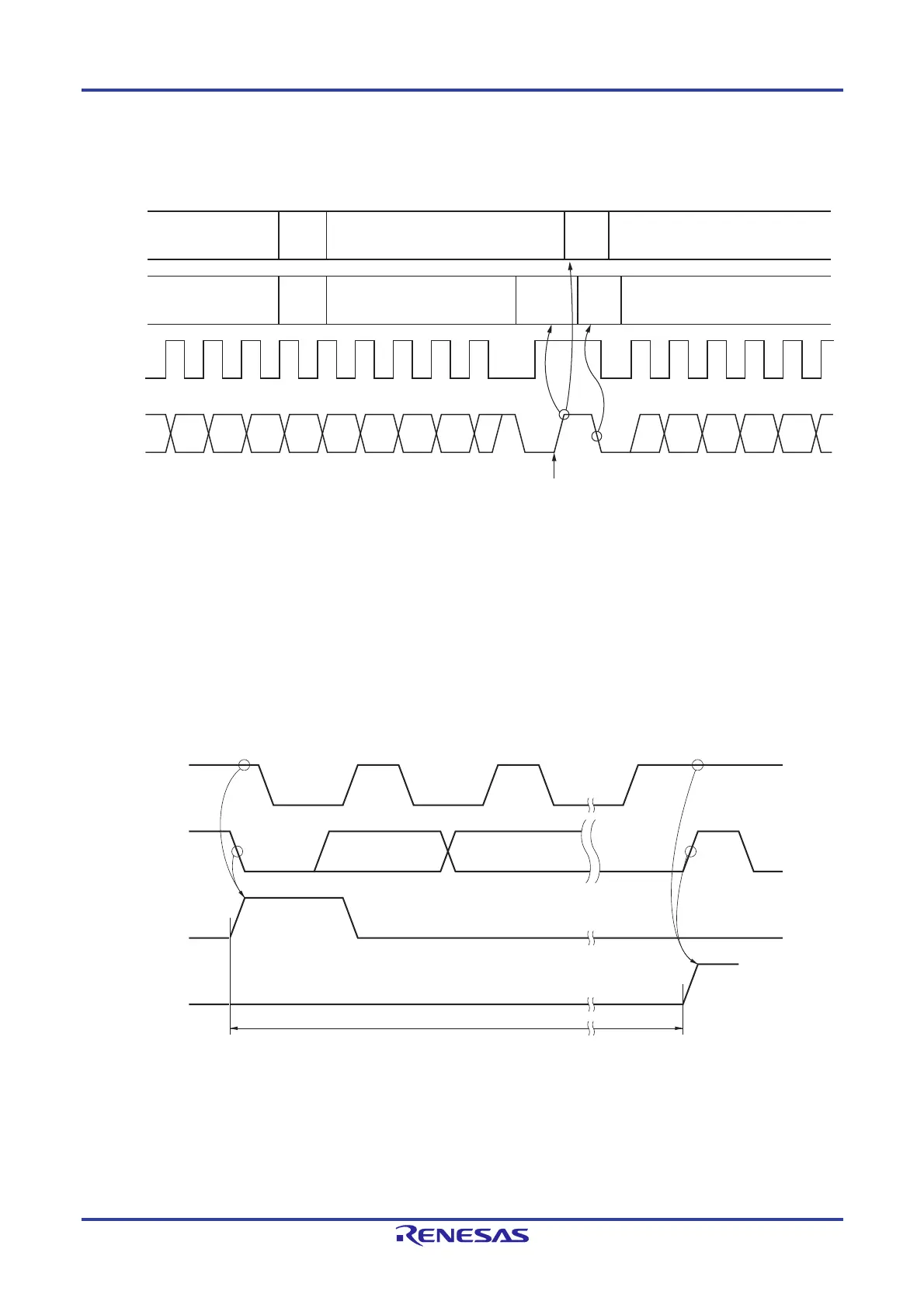
Figure 16-26 shows the communication reservation timing.
Figure 16-26. Communication Reservation Timing
Remark IICA0: IICA shift register 0
STT0: Bit 1 of IICA control register 00 (IICCTL00)
STD0: Bit 1 of IICA status register 0 (IICS0)
SPD0: Bit 0 of IICA status register 0 (IICS0)
Communication reservations are accepted via the timing shown in Figure 16-27. After bit 1 (STD0) of the IICA status
register 0 (IICS0) is set to 1, a communication reservation can be made by setting bit 1 (STT0) of IICA control register
00 (IICCTL00) to 1 before a stop condition is detected.
Figure 16-27. Timing for Accepting Communication Reservations
Figure 16-28 shows the communication reservation protocol.
213456213456789
SCLA0
SDAA0
Program processing
Hardware processing
Write to
IICA0
Set SPD0
and
INTIICA0
STT0 = 1
Communi-
cation
reservation
Set
STD0
Generate by master device with bus mastership
SCLA0
SDAA0
STD0
SPD0
Standby mode (Communication can be reserved by setting STT0 to 1 during this period.)
 Loading...


