RL78/F13, F14 CHAPTER 8 TIMER RD
R01UH0368EJ0210 Rev.2.10 585
Dec 10, 2015
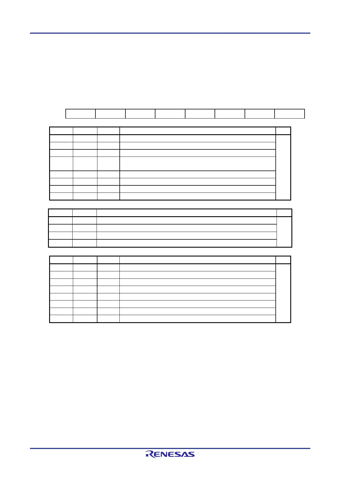
8.2.12 Timer RD Control Register i (TRDCRi) (i = 0 or 1)
The TRDCR1 register is not used in reset synchronous PWM mode or PWM3 mode.
Figure 8-16. Format of Timer RD Control Register i (TRDCRi) (i = 0 or 1)
[Input Capture Function and Output Compare Function]
Address: F0270H (TRDCR0), F0280H (TRDCR1) After Reset: 00H
Note 1
Symbol 7 6 5 4 3 2 1 0
TRDCRi CCLR2
CCLR1 CCLR0 CKEG1 CKEG0
TCK2 TCK1 TCK0
CCLR2 CCLR1 CCLR0 TRDi counter clear select R/W
0 0 0 Clear disabled (free-running operation) R/W
0 0 1 Clear by input capture/compare match with TRDGRAi
0 1 0 Clear by input capture/compare match with TRDGRBi
0 1 1 Synchronous clear (clear simultaneously with other timer RDi counter)
Note 2
1 0 0 Do not set.
1 0 1 Clear by input capture/compare match with TRDGRCi
1 1 0 Clear by input capture/compare match with TRDGRDi
1 1 1 Do not set.
CKEG1 CKEG0
External clock edge select
Note 3
R/W
0 0 Count at the rising edge R/W
0 1 Count at the falling edge
1 0 Count at both edges
1 1 Do not set.
TCK2 TCK1 TCK0 Count source select R/W
0 0 0
f
TRD
Note 4
R/W
0 0 1
f
TRD/2
Notes 4, 6
0 1 0
f
TRD/4
Notes 4, 6
0 1 1
f
TRD/8
Notes 4, 6
1 0 0
f
TRD/32
Notes 4, 6
1 0 1
TRDCLK input
Note 5
1 1 0 Do not set.
1 1 1 Do not set.
Notes 1. The value after reset is undefined when FRQSEL4 = 1 in the user option byte (000C2H/020C2H) and
TRD0EN = 0 in the PER1 register. If it is necessary to read the initial value, set f
CLK to fIH and TRD0EN
= 1 before reading.
2. Enabled when the TRDSYNC bit in the TRDMR register is 1 (TRD0 and TRD1 operate synchronously).
3. Valid when bits TCK2 to TCK0 are set to 101B (TRDCLK input) and the STCLK bit is set to 1 (external
clock input enabled).
4. As the timer RD operating clock (f
TRD), fCLK is selected when FRQSEL4 = 0 in the user option byte
(000C2H/020C2H), (PLLDIV1 = 0 or SELPLLS = 0), and TRD_CKSEL = 0. f
IH is selected when
FRQSEL4 = 1 and TRD_CKSEL = 0. f
PLL is selected when (PLLDIV1 = 1 and SELPLLS = 1) and
TRD_CKSEL = 0. fSUB is selected when SELLOSC = 0 and TRD_CKSEL = 1. fIL is selected when
SELLOSC = 1 and TRD_CKSEL = 1. For details, see Figure 8-40.
When selecting the count source for the timer RD, set the same clock source as the count source for
f
CLK before setting bit 4 (TRD0EN) in the peripheral enable register 1 (PER1).
5. Valid when the STCLK bit in the TRDFCR register is set to 1 (external clock input enabled).
6. With this setting, select fCLK as the timer RD operating clock (fTRD).

 Loading...


