RL78/F13, F14 CHAPTER 23 STANDBY FUNCTION
R01UH0368EJ0210 Rev.2.10 1522
Dec 10, 2015
23.2.3 STOP status output control register (STPSTC)
The port latch of P31 or P52 can be inverted in response to a source condition for release from the STOP mode being
generated or a transition from SNOOZE mode to normal mode.
Set the STPSTC register by a 1-bit or 8-bit memory manipulation instruction.
Writing to the STPSTC register is disabled when the GCSC bit of the IAWCTL register is set to 1.
Reset signal generation clears this register to 00H.
Cautions 1. As the 20-, 30-, and 32-pin products do not have the STOPST function, they do not have the STPSTC
register.
2. When the STOP status output control register is to be used, the target port pin should be placed in
the output mode and the port latch should be set to 0 beforehand.
Figure 23-3. Format of STOP Status Output Control Register (STPSTC)
Address: F02CAH After reset: 00H R/W
Symbol <7> 6 5 <4> 3 2 1 <0>
STPSTC STPOEN 0 0 STPLV
Note 1
0 0 0 STPSEL
Note 2
STPOEN Enabling or disabling of STOPST output
0 Nothing is done when this LSI is released from the STOP mode.
1 The STPLV value is output on the pin selected by STPSEL when this LSI is released from
the STOP mode.
STPLV
Note 1
Control of STOPST output level
0 Output low
1 Output high
STPSEL
Note 2
Control of STOPST pin selection
0 Selects P31
1 Selects P52
Notes 1. The STPLV bit is inverted when this LSI is released from the STOP mode and when this LSI
makes a transition from SNOOZE mode to normal mode.
2. Bit 0 is a read-only reserved bit in 48-pin products. When setting the register, write the initial
value, 0, to this bit.
Caution Be sure to set bits 1 to 3, 5, and 6 of the STPSTC register to 0.
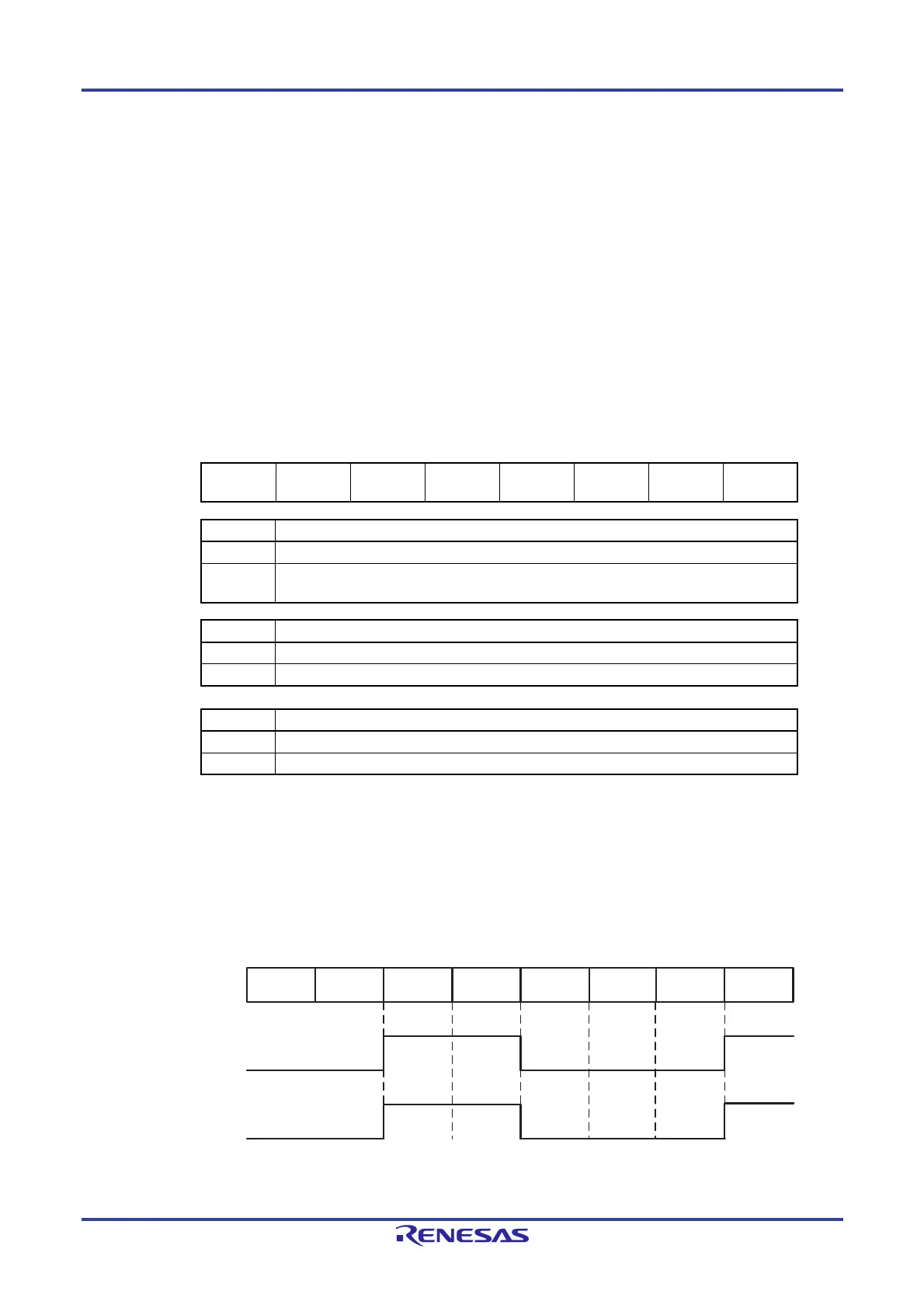
The following figure shows the timing of the STOPST pin and STPLV bit during CPU operation status.
CPU status
RUN STOP RUN RUN
STOP
SNOOZE
RUN
STOP
P31/STOPST or
P52/STOPST
STPLV
 Loading...


