RL78/F13, F14 CHAPTER 5 CLOCK GENERATOR
R01UH0368EJ0210 Rev.2.10 374
Dec 10, 2015
5.3.3 Clock Operation Status Control Register (CSC)
This register is used to control the operations of the high-speed system clock, high-speed on-chip oscillator clock, and
subsystem clock (except the low-speed on-chip oscillator clock).
Set the CSC register by a 1-bit or 8-bit memory manipulation instruction.
Writing to the CSC register is disabled when the GCSC bit of the IAWCTL register is set to 1.
Reset signal generation sets this register to C0H.
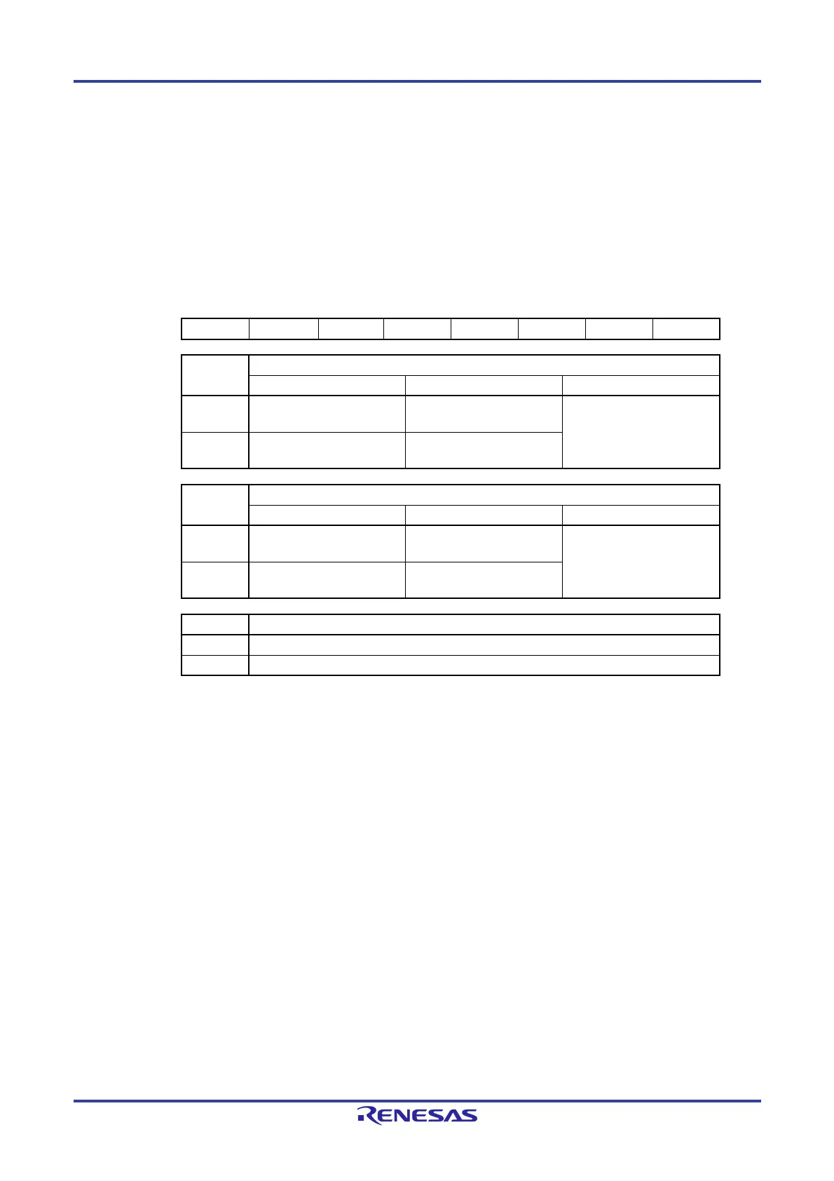
Figure 5-5. Format of Clock Operation Status Control Register (CSC)
Address: FFFA1H After reset: C0H R/W
Symbol <7> <6> 5 4 3 2 1 <0>
CSC MSTOP XTSTOP 0 0 0 0 0 HIOSTOP
MSTOP High-speed system clock operation control
X1 oscillation mode External clock input mode Input port mode
0 X1 oscillator operating External clock from EXCLK
pin is valid
Input port
1 X1 oscillator stopped External clock from EXCLK
pin is invalid
XTSTOP
Note
Subsystem clock operation control
XT1 oscillation mode External clock input mode Input port mode
0 XT1 oscillator operating External clock from EXCLKS
pin is valid
Input port
1 XT1 oscillator stopped External clock from EXCLKS
pin is invalid
HIOSTOP High-speed on-chip oscillator clock operation control
0 High-speed on-chip oscillator operating
1 High-speed on-chip oscillator stopped
Note When setting the CSC register in the 20-, 30-, or 32-pin products, use the register with the
XTSTOP bit set to 1 without changing from the default.
Cautions 1. After reset release, set the clock operation mode control register (CMC) before
setting the CSC register.
2. Set the oscillation stabilization time select register (OSTS) before setting the
MSTOP bit to 0 after releasing reset. Note that if the OSTS register is being used
with its default settings, the OSTS register is not required to be set here.
3. To start X1 oscillation as set by the MSTOP bit, check the oscillation stabilization
time of the X1 clock by using the oscillation stabilization time counter status
register (OSTC).
4. When starting XT1 oscillation by setting the XTSTOP bit, wait for oscillation of the
subsystem clock to stabilize by setting a wait time using software.
5. Do not stop the clock selected for the CPU peripheral hardware clock (f
CLK) with the
OSC register.
6. The setting of the flags of the register to stop clock oscillation (invalidate the external
clock input) and the condition before clock oscillation is to be stopped are as Table
5-2.
 Loading...


