RL78/F13, F14 CHAPTER 21 INTERRUPT FUNCTIONS
R01UH0368EJ0210 Rev.2.10 1497
Dec 10, 2015
21.3.4 External interrupt rising edge enable registers (EGP0, EGP1), external interrupt falling edge enable
registers (EGN0, EGN1)
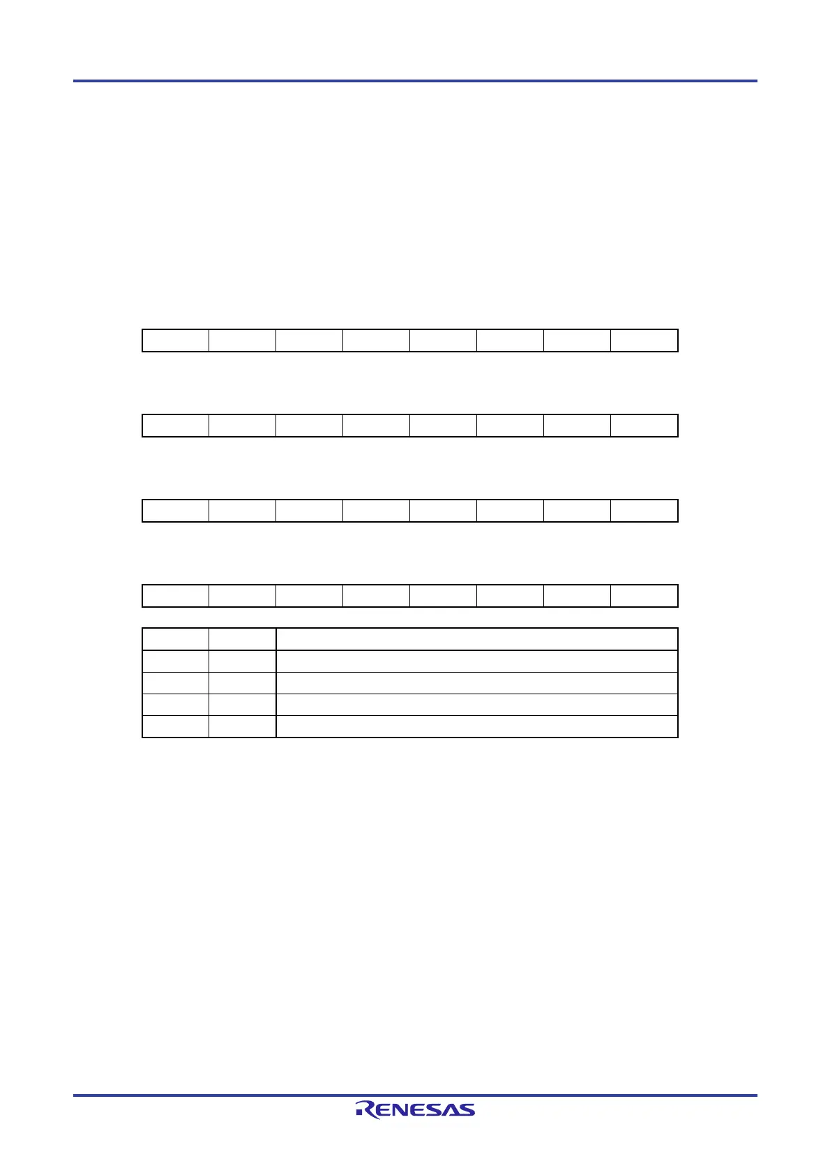
These registers specify the valid edge for INTP0 to INTP13.
The EGP0, EGP1, EGN0, and EGN1 registers can be set by a 1-bit or 8-bit memory manipulation instruction.
Reset signal generation clears these registers to 00H.
Figure 21-5. Format of External Interrupt Rising Edge Enable Registers (EGP0, EGP1) and External Interrupt
Falling Edge Enable Registers (EGN0, EGN1)
ddress: FFF38H After reset: 00H R/W
Symbol 7 6 5 4 3 2 1 0
EGP0 EGP7 EGP6 EGP5 EGP4 EGP3 EGP2 EGP1 EGP0
ddress: FFF39H After reset: 00H R/W
Symbol 7 6 5 4 3 2 1 0
EGN0 EGN7 EGN6 EGN5 EGN4 EGN3 EGN2 EGN1 EGN0
ddress: FFF3AH After reset: 00H R/W
Symbol 7 6 5 4 3 2 1 0
EGP1 0 0 EGP13 EGP12 EGP11 EGP10 EGP9 EGP8
ddress: FFF3BH After reset: 00H R/W
Symbol 7 6 5 4 3 2 1 0
EGN1 0 0 EGN13 EGN12 EGN11 EGN10 EGN9 EGN8
EGPn EGNn INTPn pin valid edge selection (n = 0 to 13)
0 0 Edge detection disabled
0 1 Falling edge
1 0 Rising edge
1 1 Both rising and falling edges
Table 21-3 shows the ports corresponding to the EGPn and EGNn bits.
 Loading...


