RL78/F13, F14 CHAPTER 12 A/D CONVERTER
R01UH0368EJ0210 Rev.2.10 728
Dec 10, 2015
Note Not provided in the RL78/F13 (LIN incorporated) products with 20, 30, 32, 48, or 64 pins and 16 Kbytes to 64
Kbytes of code flash memory.
Cautions 1. Set the port that is set to analog input by the ADPC register to the input mode by using port mode
registers 3, 8 to 10, or 12 (PM3, PM8 to PM10, PM12).
2. Do not set the pin set by the ADPC register as digital I/O by the analog input channel specification
register (ADS).
3. When using AV
REFP and AVREFM, specify ANI0 and ANI1 as the analog input channels and specify
input mode by using the port mode register.
12.3.12 A/D converter trigger select register 0 (ADTRGS0) (RL78/F13 only)
This register is used to enable or disable operation trigger generation of the A/D converter when the timer RD0 input
capture B/compare match B interrupt request is generated.
Set this register while the timer RD0 input capture B/compare match B interrupt request is not generated.
Reset signal generation clears this register to 00H.
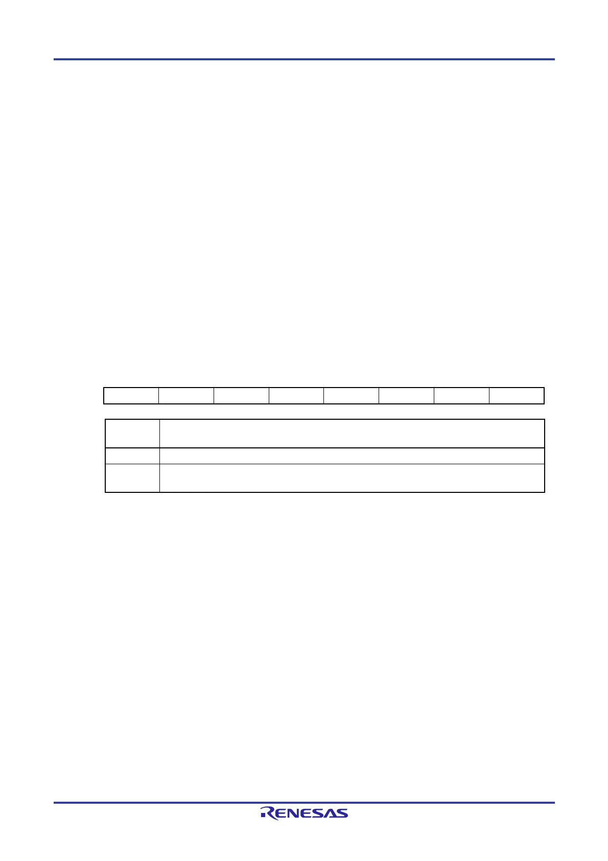
Figure 12-16. Format of A/D Converter Trigger Select Register 0 (ADTRGS0)
Address: F0789H After reset: 00H R/W
Symbol 7 6 5 4 3 2 1 0
ADTRGS0 0 0 0 0 0 0 0 ADTRGS00
ADTRGS00
Selection of the operation trigger of the A/D converter when the timer RD0 input capture B/compare match B
interrupt request is generated
0 The operation trigger of the A/D converter is not generated when the interrupt request is generated.
1
The operation trigger of the A/D converter is generated when the interrupt request is generated (A/D
conversion is started).
 Loading...


