RL78/F13, F14 CHAPTER 35 ELECTRICAL SPECIFICATIONS (GRADE K)
R01UH0368EJ0210 Rev.2.10 1758
Dec 10, 2015
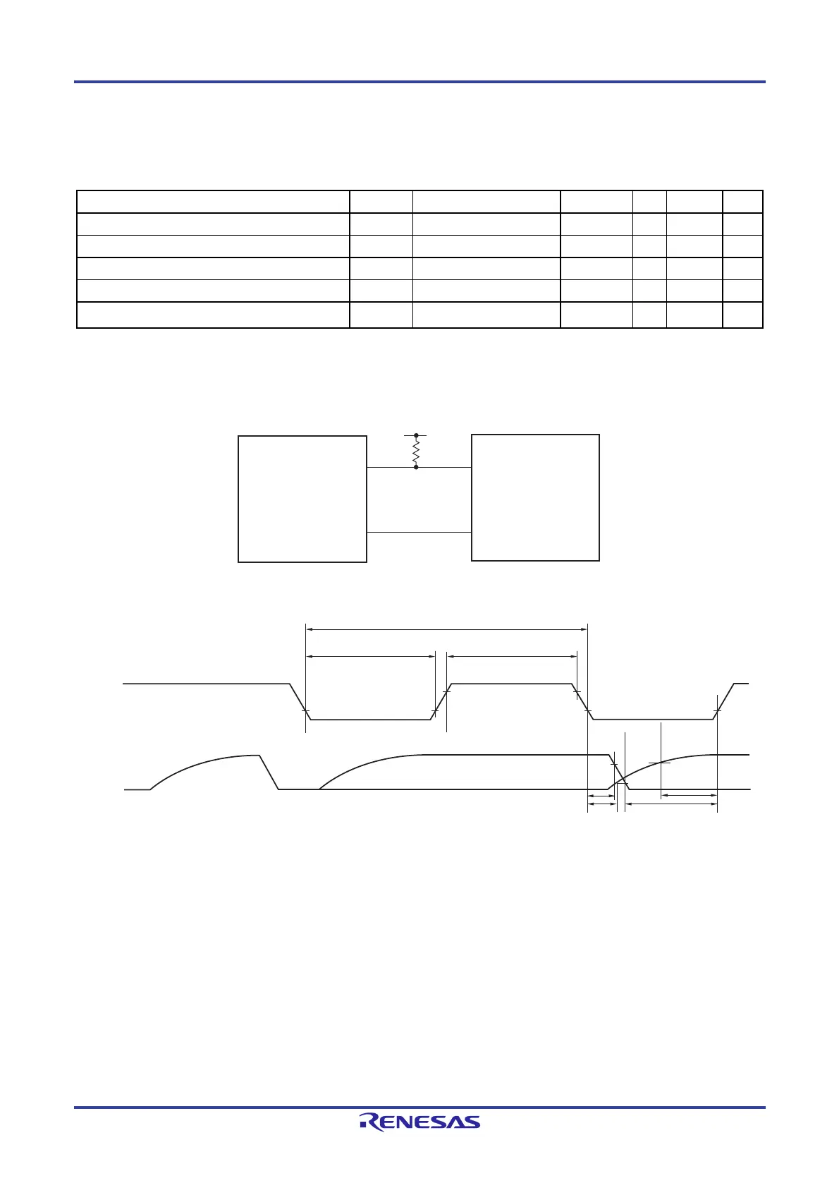
(6) During communication at same potential (simplified I
2
C mode)
(SDAr: N-ch open-drain output (EV
DD0 tolerance) mode, SCLr: normal output mode)
(TA = -40 to +125C, 2.7 V EVDD0 = EVDD1 = VDD 5.5 V, VSS = EVSS0 = EVSS1 = 0 V)
Parameter Symbol Conditions MIN. TYP. MAX. Unit
SCLr clock frequency fSCL
1000
Note
kHz
Hold time when SCLr = ”L” tLOW
475 ns
Hold time when SCLr = ”H” tHIGH
475 ns
Data setup time (reception) tSU:DAT
1/f
MCK + 85 ns
Data hold time (transmission) tHD:DAT
C
b = 50 pF, Rb = 2.7 k 0 305 ns
Note fCLK fMCK/4 must also be satisfied.
Simplified I
2
C mode connection diagram (during communication at same potential)
Simplified I
2
C mode serial transfer timing (during communication at same potential)
Caution Select the normal input buffer and N-ch open-drain output mode for the SDAr pin and normal output
mode for the SCLr pin.
Remarks 1. R
b [Ω]: Communication line (SDAr) pull-up resistance, Cb [F]: Communication line (SCLr, SDAr) load
capacitance
2. r: IICr (r = 00, 01, 10, 11)
3. f
MCK: Serial array unit operation clock frequency
SDAr
SCLr
SDA
SCL
User's device
VDD
Rb
RL78
microcontroller
SDAr
t
LOW
t
HIGH
1/f
SCL
t
HD : DAT
SCLr
t
SU : DAT
 Loading...


