RL78/F13, F14 CHAPTER 5 CLOCK GENERATOR
R01UH0368EJ0210 Rev.2.10 376
Dec 10, 2015
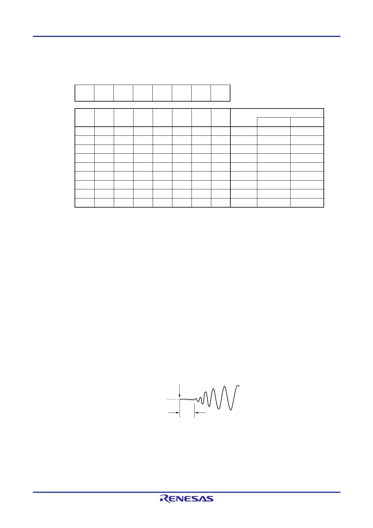
Figure 5-6. Format of Oscillation Stabilization Time Counter Status Register (OSTC)
Address: FFFA2H After reset: 00H R
Symbol 7 6 5 4 3 2 1 0
OSTC MOST
8
MOST
9
MOST
10
MOST
11
MOST
13
MOST
15
MOST
17
MOST
18
MOST
8
MOST
9
MOST
10
MOST
11
MOST
13
MOST
15
MOST
17
MOST
18
Oscillation stabilization time status
fX = 10 MHz fX = 20 MHz
0 0 0 0 0 0 0 0 2
8
/fX max. 25.6
s max. 12.8
s max.
1 0 0 0 0 0 0 0 2
8
/fX min. 25.6
s min. 12.8
s min.
1 1 0 0 0 0 0 0 2
9
/fX min. 51.2
s min. 25.6
s min.
1 1 1 0 0 0 0 0 2
10
/fX min. 102.4
s min. 51.2
s min.
1 1 1 1 0 0 0 0 2
11
/fX min. 204.8
s min. 102.4
s min.
1 1 1 1 1 0 0 0 2
13
/fX min. 819.2
s min. 409.6
s min.
1 1 1 1 1 1 0 0 2
15
/fX min. 3.27 ms min. 1.63 ms min.
1 1 1 1 1 1 1 0 2
17
/fX min. 13.10 ms min. 6.55 ms min.
1 1 1 1 1 1 1 1 2
18
/fX min. 26.21 ms min. 13.10 ms min.
Cautions 1. After the above time has elapsed, the bits are set to 1 in order from the MOST8
bit and remain 1.
2. The oscillation stabilization time counter counts up to the oscillation
stabilization time set by the oscillation stabilization time select register (OSTS).
In the following cases, set the oscillation stabilization time of the OSTS register
to the value equal to or greater than the count value which is to be checked by
the OSTC register.
If the X1 clock starts oscillation while the high-speed on-chip oscillator clock
or subsystem clock is being used as the CPU clock.
If the STOP mode is entered and then released while the high-speed on-chip
oscillator clock is being used as the CPU clock with the X1 clock oscillating.
(Note, therefore, that only the status up to the oscillation stabilization time
set by the OSTS register is set to the OSTC register after the STOP mode is
released.)
3. The X1 clock oscillation stabilization wait time does not include the time until
clock oscillation starts (“a” below).
STOP mode release
X1 pin voltage
waveform
a
 Loading...


