RL78/F13, F14 CHAPTER 6 TIMER ARRAY UNIT
R01UH0368EJ0210 Rev.2.10 534
Dec 10, 2015
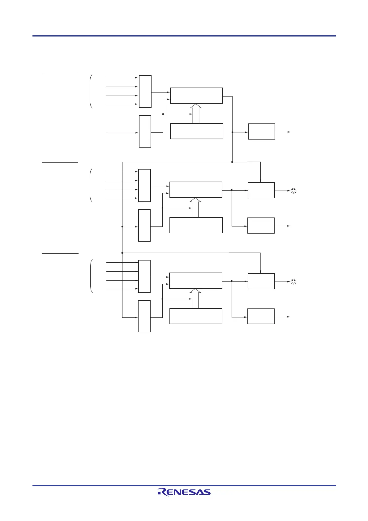
Figure 6-77. Block Diagram of Operation as Multiple PWM Output Function (output two types of PWMs)
Remarks 1. m: Unit number (m = 0, 1), n: Master channel number (n = 0, 2, 4)
p: Slave channel number 1, q: Slave channel number 2
n < p < q 7 (Where p and q are integers greater than n)
2. Unit 1 is not provided in the Group A products.
Channels 7 to 4 of unit 1 are not provided in the Group B, C, and D products.
Interrupt signal
(INTTMmn)
Interrupt
controller
Clock selection
Trigger selection
TSmn
Interrupt signal
(INTTMmp)
Interrupt
controller
Clock selection
Trigger selection
TOmp pin
Output
controller
Master channel
(interval timer mode)
Slave channel 1
(one-count mode)
Interrupt signal
(INTTMmq)
Interrupt
controller
Clock selection
Trigger selection
TOmq pin
Output
controller
Slave channel 2
(one-count mode)
Timer counter
register mn (TCRmn)
Timer data
register mn (TDRmn)
Timer counter
register mp (TCRmp)
Timer data
register mp (TDRmp)
Timer counter
register mq (TCRmq)
Timer data
register mq (TDRmq)
CKm2
CKm3
Operation clock
CKm0
CKm1
CKm2
CKm3
Operation clock
CKm0
CKm1
CKm2
CKm3
Operation clock
CKm0
CKm1
 Loading...


