10 Instrument setup
Roche Diagnostics
COBAS INTEGRA 400 plus analyzer/Cedex Bio HT Analyzer · Software version 3.6/5.1 · Host Interface Manual · Version 1.24
Instrument setup 187
q Please ensure that the suggested wiring matches
the host system requirements as well.
Some host systems are configured as DCE devices. TxD
and RxD are then exchanged.
About the connector types
About the cable types
Type To reduce electromagnetic interference, we recommend
using shielded twisted pair cables having low inductance.
Shield We recommend connecting the cable shield to the SUB-D
chassis of the interface connector on one side only.
q NEVER connect the cable shield to the signal
ground.
Connector housing To prevent electromagnetic interference, we strongly
recommend using a true metal connector housing, not
connector housings of plastic.
Length The cable length should not exceed 15 m.
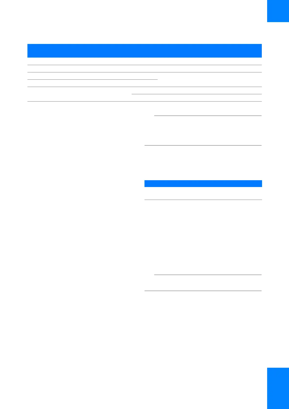
420DTRffDSR 6 6
6 6 DSR ggDTR 20 4
7 4 RTS f
f DCD 8 1
8 5 CTS g
1 8 DCD g
g RTS 4 7
f CTS 5 8
Host (DTE) Instrument (DTE)
9 Pin Conn 25 Pin Conn Signal I/O I/O Signal 25 Pin Conn. 9 Pin Conn
y Pin assignments for RS-232 HW-handshaking
Instrument Connector type
COBAS INTEGRA 400 plus analyzer
and Cedex Bio HT Analyzer
SUB-D male type, 9 pin
y Connector types