112 Rockwell Automation Publication 5094-UM001C-EN-P - April 2019
Chapter 7 Configure and Replace Safety Modules
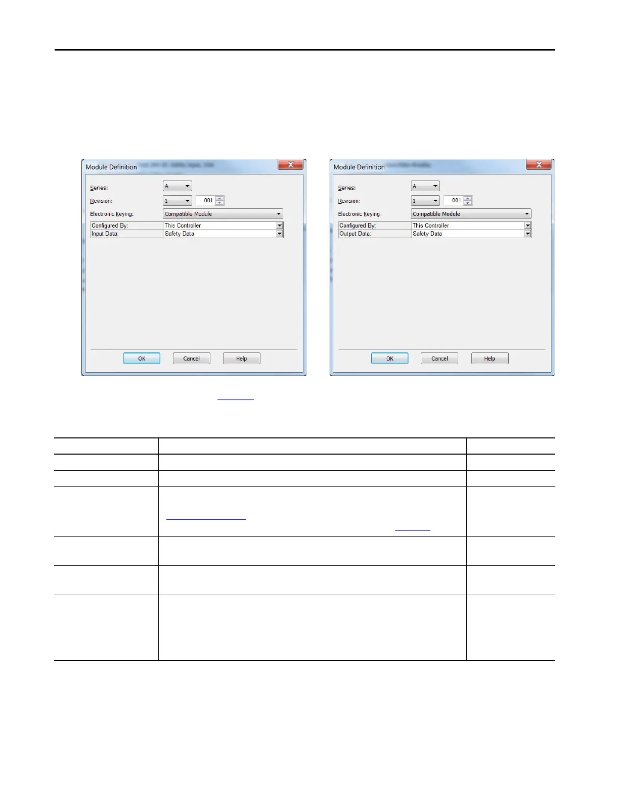
Module Definition
Module Definition parameters are available on the General tab of the Module
Properties dialog box in the Logix Designer application project.
Tabl e 17
describes the parameters that are available on the Module Definition
dialog box.
5094-IB16S and 5094-IB16SXTModules
5094-OB16S and 5094-OB16SXTModules
Table 17 - Module Definition Parameters
Parameter Definition Available Choices
Series Module hardware series Module-specific
Revision Module firmware revision, including major and minor revision levels Module-specific
Electronic Keying Software method by which you reduce the possibility of using the wrong device in a control system.
For more information, see the following:
• Electronic Keying on page 27
• Electronic Keying in Logix5000 Control Systems Application Technique, publication LOGIX-AT001
• Exact Match
• Compatible Module
Configured By Determines the following for the module type you configure:
• Which controller tags are generated when configuration is complete
• This Controller
•External Means
(1)
Input Data Determines what type of input data is exchanged between the module and the controller.
Creates all controller tags specific to the module type being used.
•Safety data
• Safety packed data
Output Data - 5094-OB16S and
5094-OB16SXT modules only
Determines what type of output data is exchanged between the module and the controller.
The available choices are dictated by the Configured By parameter choice.
• None - If Configured By is
External Means.
• Safety data and Safety
packed data - If
Configured By is This
Controller.
(1) Controller and module establish communication without the controller sending any configuration or output data to the module. A full input data connection is established but depends on the
connection between the owner-controller and the module.

 Loading...


