Rockwell Automation Publication 2071-UM001E-EN-P - November 2013 65
Connect the Kinetix 3 Drive Chapter 4
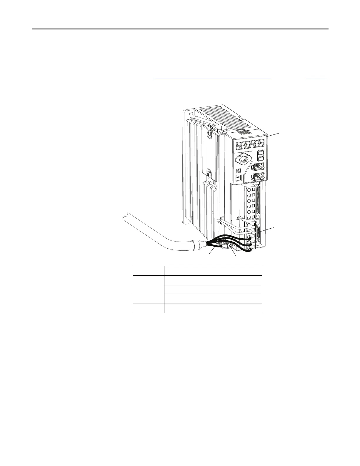
This diagram shows an example of three-phase power wires for TL-Series
(Bulletin TL) motors that have no brakes. Thermal switch wires are included in
the feedback cable.
Refer to Kinetix 3 Drive/Rotary Motor Wiring Examples
beginning on page 124
for interconnect diagrams.
Figure 33 - Motor Power Terminations (Bulletin TL three-phase wires only)
Cable shield is tied to the ground wire in the cable. No further grounding is
required with motor power cable, catalog number 2090-DANPT-16Sxx.
Item Description
1
2071-AP4 Kinetix 3 drive shown
2
Motor power (MP) connector plug
3
Drive ground screw
4
Motor cable ground wire
 Loading...


