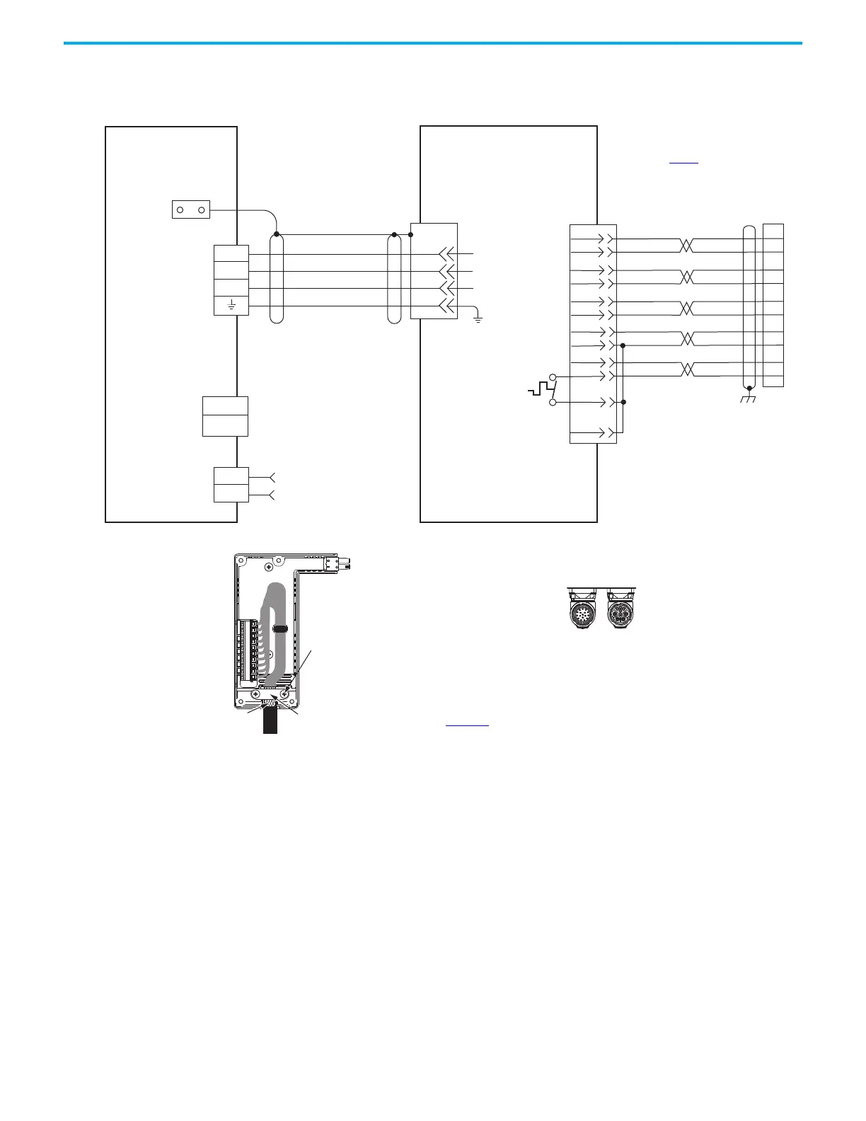
power/brake and feedback connections.
Motor Brake
(BC) Connector
Motor Power
(MP) Connector
LDAT-Sxxxxxx-xDx
Linear Thrusters with
High-Resolution Feedback
Motor Feedback
(MF) Connector
Three-phase
Motor Power
Motor
Feedback
Thermostat
Grounding Technique for
Feedback Cable Shield
Cable Clamp
Exposed shield secured
under clamp.
Clamp Screws (2)
See table on page 179 for note information.
2198-H2DCK Feedback
Converter Kit
Cable Shield
Clamp
Note 5
2198-Hxxx-Erse
Kinetix 5500 Servo Drives
See Hiperface to DSL Feedback Converter Kit Installation Instructions,
publication 2198-IN006
, for converter kit specifications.
Power Connector
Feedback Connector
SpeedTec DIN
Motor Connectors
2090-CFBM7DF-CEAAxx (standard) or
2090-CFBM7DF-CEAFxx (continuous-flex)
(flying lead) Feedback Cable
Notes 11, 12, 13
2090-CPWM7DF-xxAAxx
(standard) or
2090-CPWM7DF-xxAFxx
(continuous-flex)
Motor Power Cable
Notes 11, 15
See DSL feedback converter kit
illustration (lower left)
for proper grounding technique.
2198-H2DCK
Hiperface-to-DSL
Feedback Converter Kit

 Loading...


