Motor Brake
Motor Brake
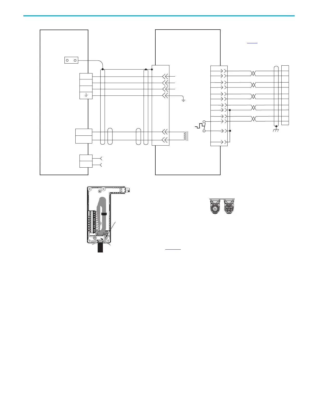
(BC) Connector
Motor Power
(MP) Connector
MPAS-A/Bxxxxx-VxxSxA
Ballscrew Linear Stages with
High-Resolution Feedback
Motor Feedback
(MF) Connector
Three-phase
Motor Power
Motor
Feedback
Thermostat
Grounding Technique for
Feedback Cable Shield
Cable Clamp
Exposed shield secured
Clamp Screws (2)
See table on page 179 for note information.
2198-H2DCK Feedback
Converter Kit
Cable Shield
Clamp
Note 5
2198-Hxxx-ERSx
Kinetix 5500 Servo Drives
See Hiperface to DSL Feedback Converter Kit Installation Instructions,
publication 2198-IN006
, for converter kit specifications.
Power Connector
Feedback Connector
SpeedTec DIN
Motor Connectors
2090-CFBM7DF-CEAAxx (standard) or
2090-CFBM7DF-CEAFxx (continuous-flex)
(flying lead) Feedback Cable
Notes 11, 12, 13
2090-CPxM7DF-xxAAxx
(standard) or
2090-CPxM7DF-xxAFxx
(continuous-flex)
Motor Power Cable
See DSL feedback converter kit
illustration (lower left)
for proper grounding technique.
2198-H2DCK
Hiperface-to-DSL
Feedback Converter Kit

 Loading...


