Protocol Analysis
R&S
®
RTM20xx
156User Manual 1317.4726.02 ─ 01
The data bits of a message are grouped by following criteria:
●
A word contains a number of successive bits. The word length is defined in the pro-
tocol configuration.
●
A frame contains a number of successive words, at least one word.
For SPI buses, the R&S RTM provides the following trigger possibilities:
●
On frame start or frame end
●
On a specified bit in the message
●
On a serial pattern
11.2.2 SPI/SSPI Bus Configuration
● Configuring SPI Buses..........................................................................................156
● SPI/SSPI Configuration Settings...........................................................................157
11.2.2.1 Configuring SPI Buses
You define the input channels for the lines and some bit information on the message.
1. Press the PROTOCOL LOGIC key on the front panel.
2. If the "Logic" menu is displayed, press "Protocol".
3. Press the "Bus Type" softkey and select "SPI" or "SSPI".
4. Press "Configuration".
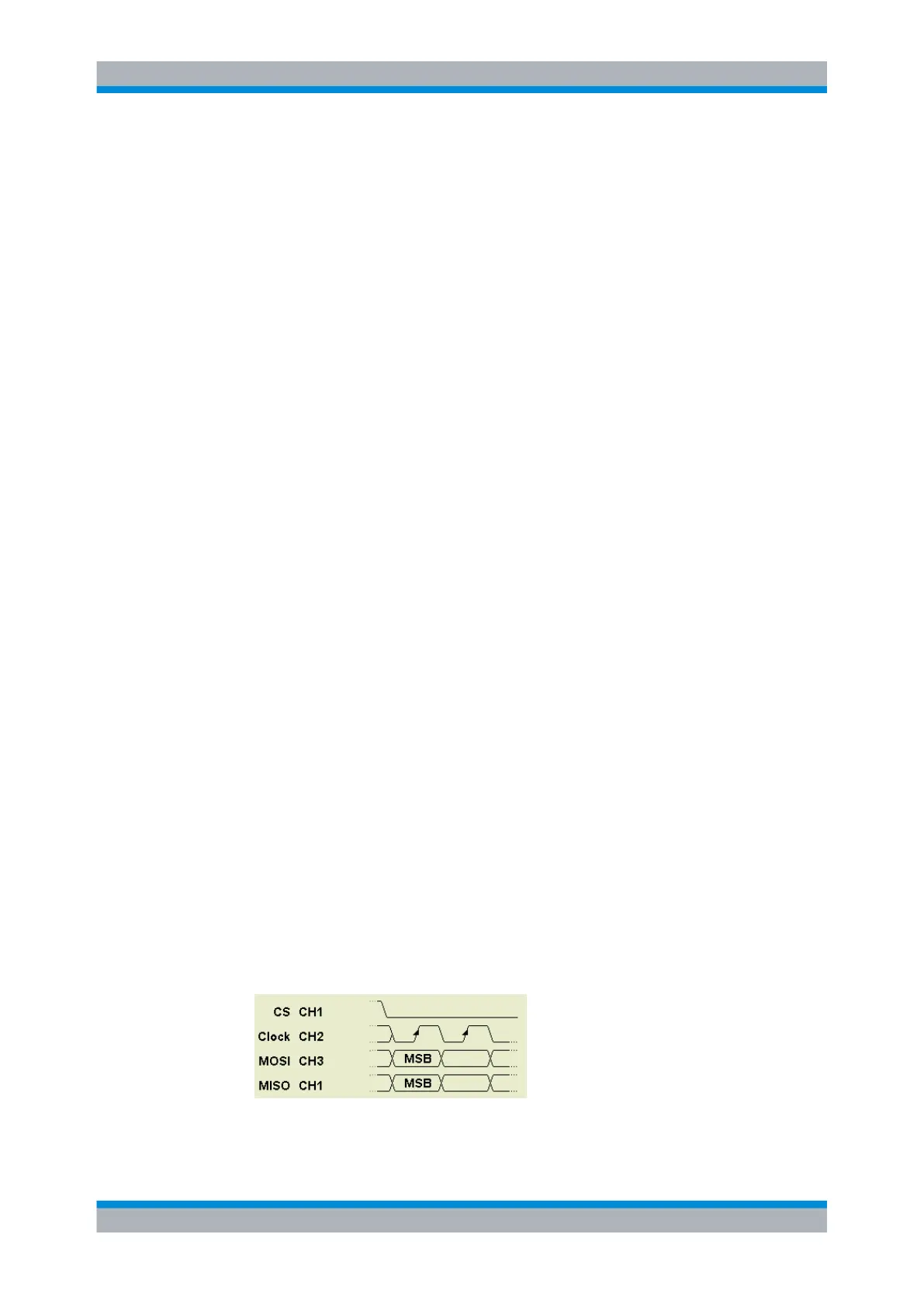
5. Press "Source" and select "Clk".
6. Press "Clock" and select the input channel of the clock. Select the "Slope".
7. Press "Source" and select "MOSI".
8. Press "MOSI" and select the input channel. With "Active", select the active state of
the data - high or low.
9. If required, repeat steps 6 and 7 for the optional MISO line.
10. For SPI, press "Source" and select "CS". Enter the input channel with "Chip Select"
and set the "Active" state.
11. For SSPI, press "Source" and select "Time". Enter the "Idle Time".
12. Set the "First Bit" and the "Symbol Size".
13. Press "Find level", or set the threshold manually for each channel.
SPI/SSPI Bus (Option R&S RTM-K1)

 Loading...


