DK00026.fm
REPAIR MANUAL
BRP-Powertrain
Effectivity: 125 MAX/125 Junior MAX/125 Mini
MAX/125 Micro MAX
Edition 2 / Rev. 0
Chapter 4
Page 9
December 01/2010
Figure 3 K00026
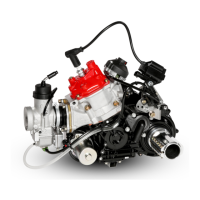
2.2.7) Removal of exhaust valve (125 MAX only)
General The engine has a pneumatic exhaust outlet control to optimize the per-
formance characteristics. The exhaust pressure controls the valve bel-
lows via the impulse bore. The exhaust valve piston pulls up the exhaust
valve and thus provides a longer outlet control time. This increases the
filling of the cylinder and increases the power.
Adjustment to determine the optimum opening of the exhaust valve can
only take place under load - on the track, during actual operation. The
exhaust gas temperature and exhaust pressure have a decisive influence
on the opening behavior of the exhaust valve. The temperature curves
during driving operation are completely different to those obtained on the
engine test stand and during idling. Therefore the adjustment and
changes to the adjustment of the exhaust valve during idling are not suit-
able for predicting performance behavior during actual driving operation.
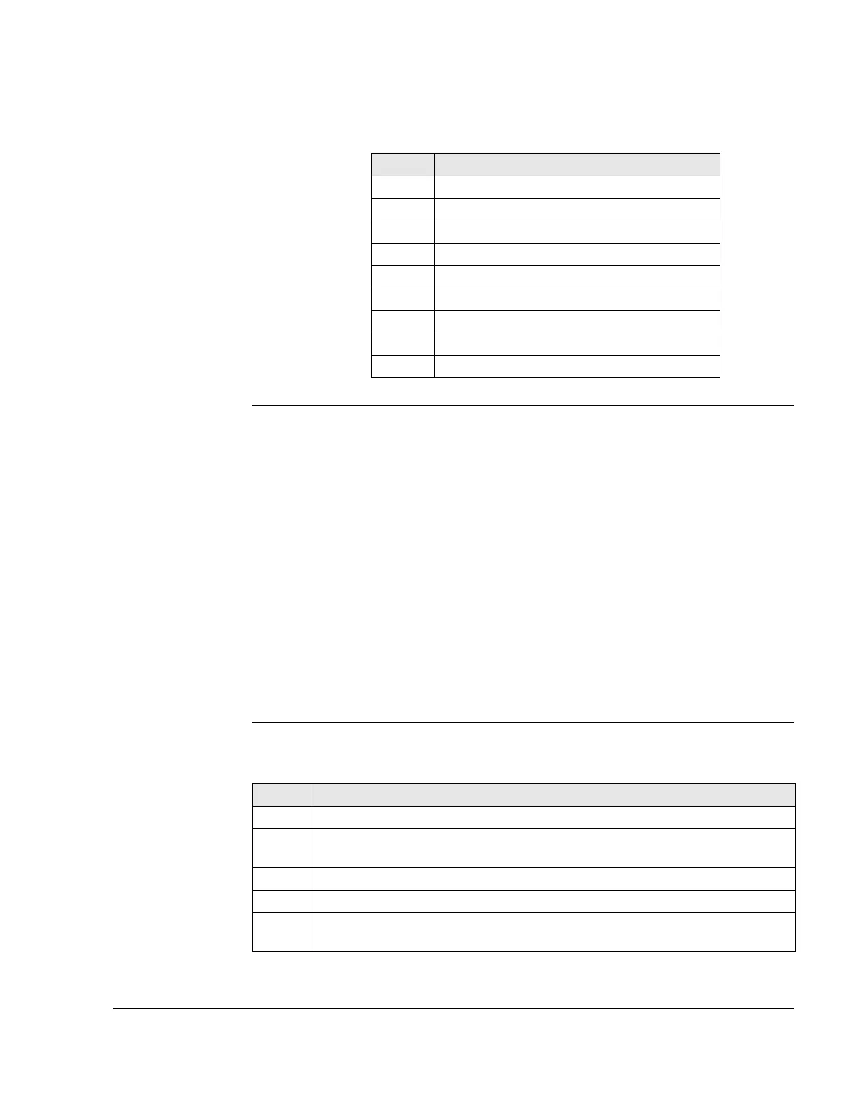
Exhaust valve See Figure 4.
Proceed as follows to remove the exhaust valve:
Part Function
1 Cylinder
2 Exhaust socket
3 Cyl. screw M8x20
4 Gasket
5 Carburetor flange
6 Hose clamp 51
7 Cyl. screw M6x25
8 Reed valve
9 Gasket
Step Procedure
1 Release the spring clip (1).
2 Remove the valve cover (2) with adjustment screw (3) and the pressure
spring (4).
3 Lift away the outer hose spring (5).
4 Unscrew the exhaust valve piston (6).
5 Remove the inner hose spring (7) from the bellows (8), push out the valve bel-
lows from the valve piston.