EasyManuals Logo

Rotax 125 Micro MAX User Manual

Rotax 125 Micro MAX
199 pages
To Next Page IconTo Next Page
To Previous Page IconTo Previous Page
Page #95 background imageLoading...
Page #95 background image
DK00027.fm
REPAIR MANUAL
BRP-Powertrain
Effectivity: 125 MAX/125 Junior MAX/125 Mini
MAX/125 Micro MAX
Edition 2 / Rev. 0
Chapter 5
Page 6
December 01/2010
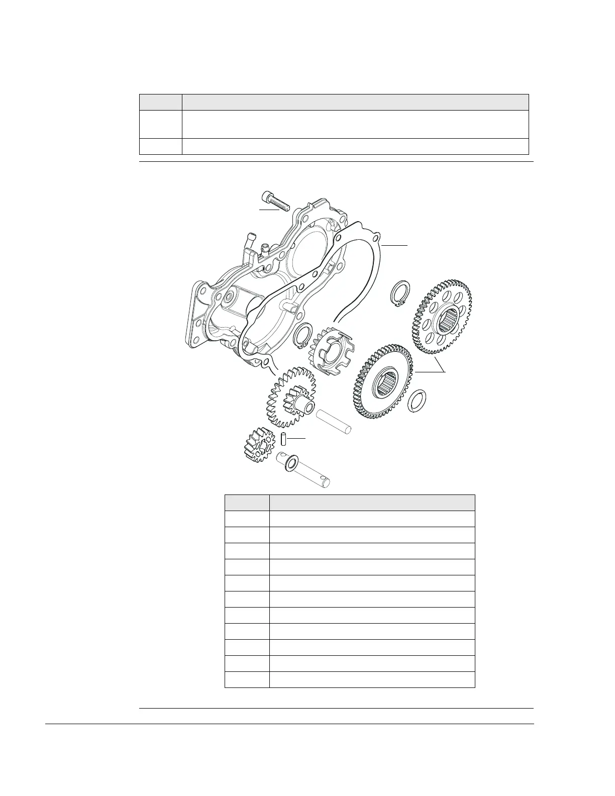
Graphic Water pump and balance shaft
Figure 2
K00067
7 Heat balance gear (10) evenly with hot air if they do not move freely and re-
move them from crankshaft or balance shaft.
8 Remove O-ring (11) from the crankshaft.
Step Procedure
Part Function
1 Cyl. screw M6x25
2 Gearbox cover
3 Gasket
4 Water-pump pinion
5 Idle gear
6 Needle pin
7 Thrust washer 10.1/17/1
8 Circlip AV 20
9 Drive gear
10 Balance gears
11 O-ring 18x3.5
2
1
3
4
5
6
7
8
8
9
11
10

Table of Contents

Questions and Answers:

Question and Answer IconNeed help?

Do you have a question about the Rotax 125 Micro MAX and is the answer not in the manual?

Rotax 125 Micro MAX Specifications

General IconGeneral
BrandRotax
Model125 Micro MAX
CategoryEngine
LanguageEnglish

Related product manuals