Installation manual
15
RRLQ006~008BBV3
Outdoor unit for air to water heat pump
4PW68222-1 – 02.2011
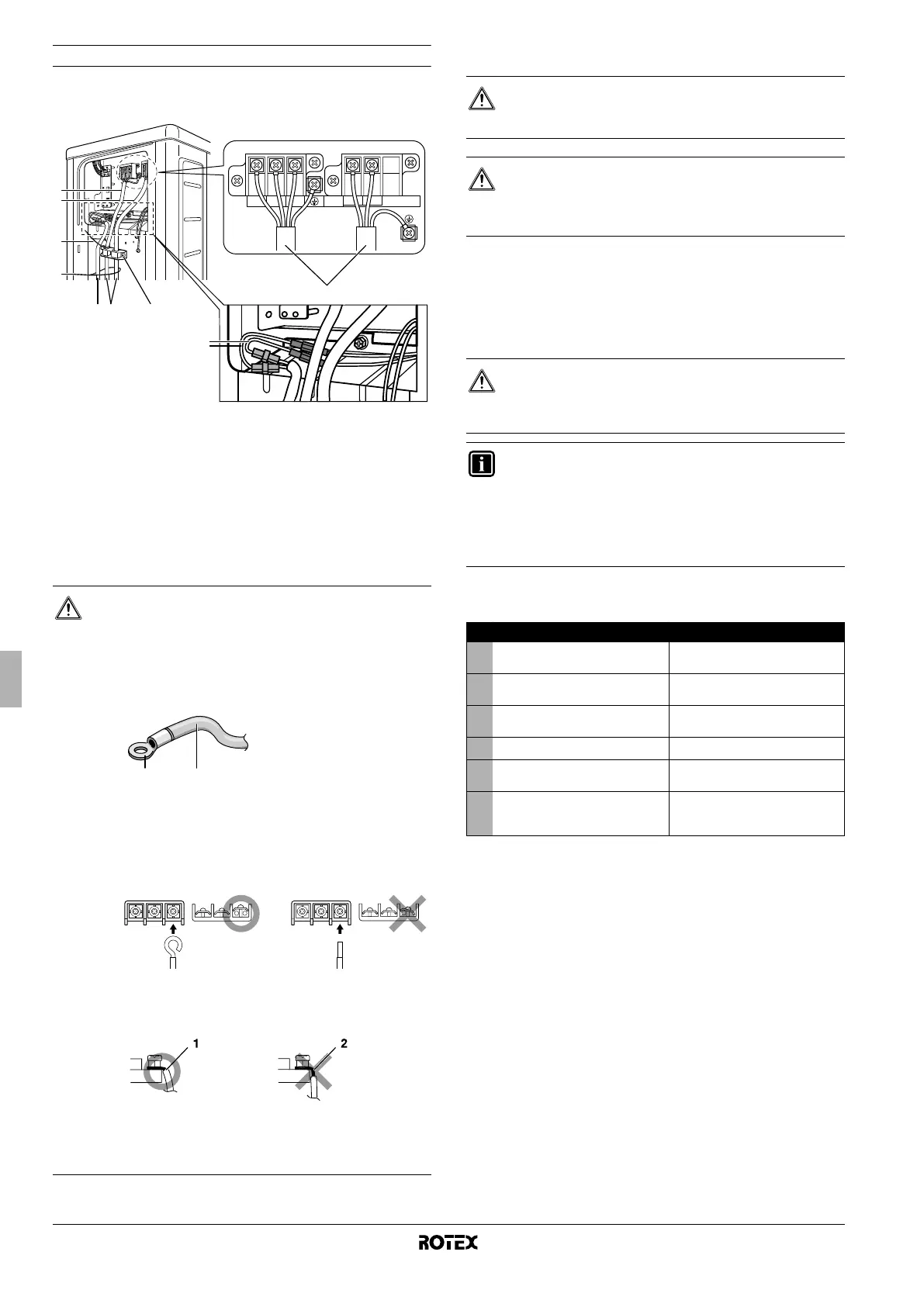
Notes to observe
Observe the notes mentioned below when wiring to the power supply
terminal board.
1 Interconnection
2 Power supply cable
3 Bottom plate heater power supply cable
4 Tie wrap
5 Bottom plate heater cable
■ Use the specified wire type and connect it securely (A).
■ Firmly secure the wire clamp so that wire terminations do not
receive external stress (B).
■ Shape wires so that the service cover and stop valve cover fit
securely (C).
14.4. Electrical characteristics
The wiring diagram can be found on the inside of the front plate of the
unit.
15. TEST OPERATION
15.1. Pre-run checks
CAUTION
1. In case the use of stranded conductor wires is
unavoidable for one reason or another, make sure to
install round crimp-style terminals on the tip.
Place the round crimp-style terminal on the wire up to
the covered part and fasten the terminal with the
appropriate tool.
2. When connecting the connection wires to the terminal
board using a single core wire, be sure to perform
curling.
Not executing the connections properly may cause
heat and fire.
Strip the wire at terminal block:
L N
123
C
A3
1
4
5
4
2
B
21
1 Stranded conductor wire
2 Round crimp-style terminal
1 Strip wire end to this point
2 Excessive strip length may cause electrical
shock or leakage.
CAUTION
Select all cables and wire sizes in accordance with
applicable legislation.
CAUTION
After finishing the electrical work, confirm that each electric
part and terminal inside the electric part box is connected
securely.
DANGER
Never leave the unit unattended during installation or
servicing. When the service panel is removed live parts
can be easily touched by accident..
INFORMATION
Note that during the first running period of the unit,
required power input may be higher than stated on the
nameplate of the unit. This phenomenon originates from
the compressor that needs elapse of a 50 hours run in
period before reaching smooth operation and stable power
consumption.
Check Symptom
■
Outdoor unit is installed properly
on solid base.
Fall, vibration, noise
■
No refrigerant gas leaks. Incomplete cooling/heating
function
■
Refrigerant gas and liquid pipes
are thermally insulated.
Water leakage
■
System is properly earthed. Electrical leakage
■
The specified wires are used for
interconnecting wire connections.
Inoperative or burn damage
■
Outdoor unit air intake and
exhaust is free of obstructions.
Stop valves are opened.
Incomplete cooling/heating
function
 Loading...